

Linear electromagnetic pumping unit
A linear motor and linear electromagnetic technology, applied in the direction of electrical components, electromechanical devices, electric components, etc., can solve the problems of high energy consumption, difficulty in changing stroke and inertial load, etc.
- Summary
- Abstract
- Description
- Claims
- Application Information
AI Technical Summary
Problems solved by technology
Method used
Image

Examples
specific Embodiment approach 1
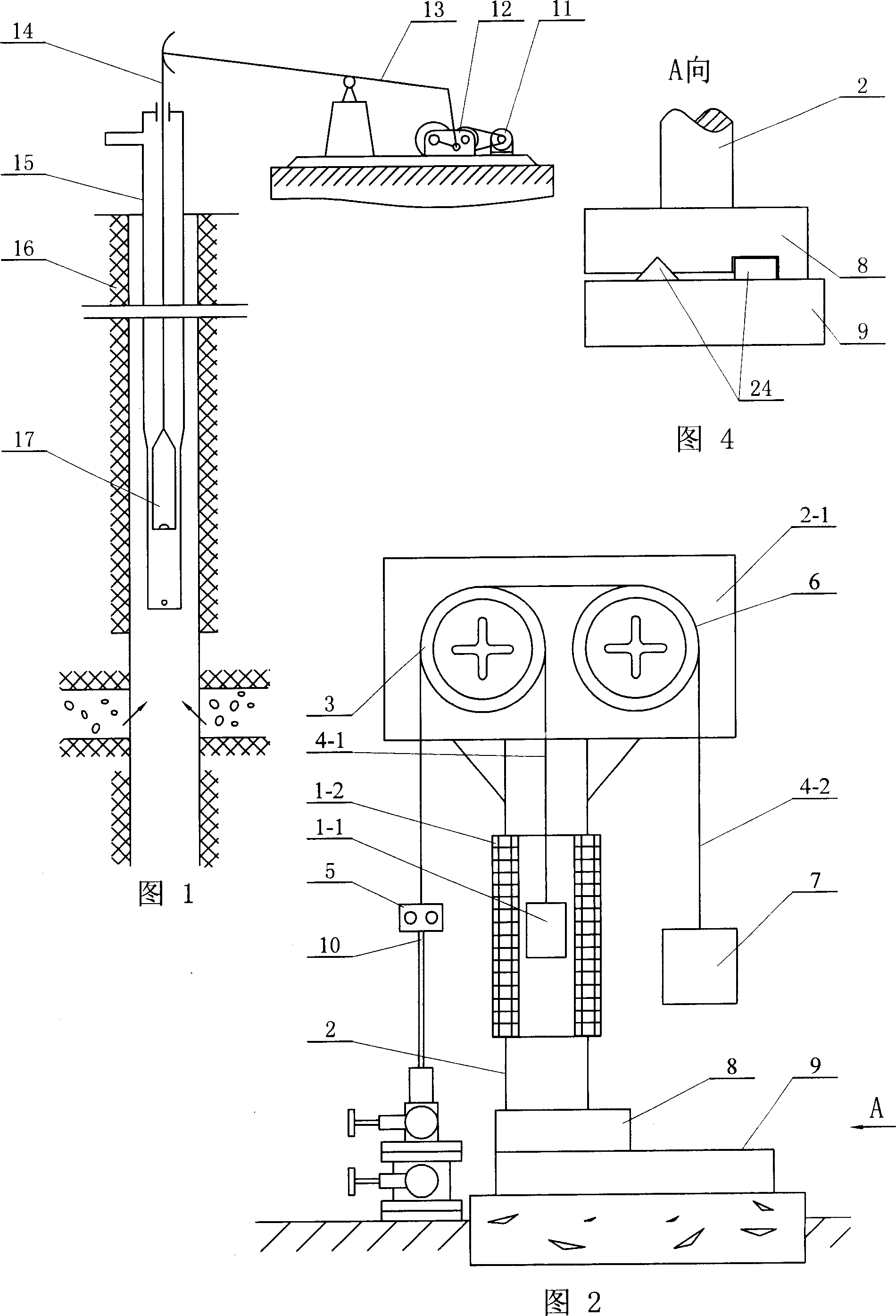
[0005] Specific implementation mode 1: This implementation mode will be specifically described below with reference to FIG. 2 . This embodiment is composed of a linear motor, a frame 2, a composite guide wheel 3, two steel wire ropes, a rope hanger 5, a balance guide wheel 6, a balance weight 7, and a base 9, and the composite guide wheel 3 and the balance guide wheel 6 are respectively arranged On both ends of the upper beam 2-1 of the "T" shaped frame 2, the rotation shafts of the composite guide wheel 3 and the balance guide wheel 6 are all set in the horizontal direction, and one end of the first steel wire rope 4-1 is connected to the second steel wire rope One end of 4-2 is fixed on the rope hanger 5, the other end of the first steel wire rope 4-1 goes around the outer circular wheel body of the composite guide wheel 3 and is fixed on the mover 1-1 of the linear motor, the second steel wire rope The other end of 4-2 bypasses the outer circular wheel body of the balance g...
specific Embodiment approach 2
[0006] Specific Embodiment 2: The present embodiment will be specifically described below with reference to FIG. 2 . The difference between this embodiment and Embodiment 1 is that the linear motor is a multi-phase permanent magnet synchronous linear motor, a multi-phase induction linear motor, a multi-phase switched reluctance linear motor or a multi-phase induction sub-linear motor.
specific Embodiment approach 3
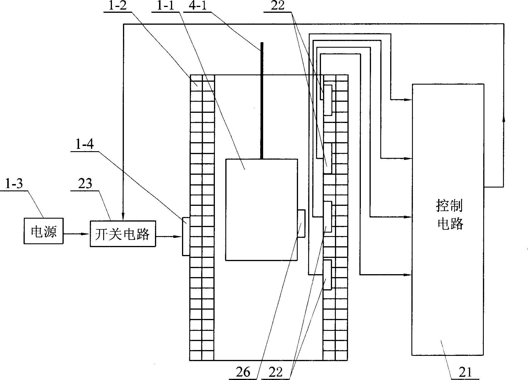
[0007] Specific implementation mode three: the following combination image 3 This embodiment will be specifically described. The difference between this embodiment and Embodiment 1 is that it also includes a control circuit 21, a switch circuit 23, a permanent magnet 26 and several Hall sensors 22, and all Hall sensors 22 are along the height of the stator 1-2 of the linear motor. The directions are uniformly arranged on the inner surface of the stator 1-2, and the permanent magnet 26 is arranged on the outer surface of the mover 1-1 at a position corresponding to the Hall sensor 22, and the signal output terminals of all the Hall sensors 22 are respectively connected to On the input end of control circuit 21, the output end of control circuit 21 is connected on the control end of switch circuit 23, and the input end of switch circuit 23 is connected the output end of the power supply 1-3 of linear motor, and the output end of switch circuit 23 is connected On the power termi...
PUM
 Abstract
Description
Claims
Application Information