Real-time body blood viscosity measuring instrument

A blood viscosity, real-time detection technology, applied in the direction of direct current flow characteristics measurement, biological testing, material inspection products, etc., can solve the problem of large blood consumption, and achieve simple operation, clear reading error, detection accuracy and high degree of automation Effect

Inactive Publication Date: 2006-10-18
INST OF MECHANICS - CHINESE ACAD OF SCI
View PDF2 Cites 19 Cited by
  • Summary
  • Abstract
  • Description
  • Claims
  • Application Information

AI Technical Summary

Problems solved by technology

[0005] The purpose of the present invention is: to overcome the large amount of blood used in the existing blood viscosity measuring instrument, and the ordinary trace liquid viscosity measuring device has not been integrated, and is only suitable for use by professionals in

Method used


Image

  • Real-time body blood viscosity measuring instrument
  • Real-time body blood viscosity measuring instrument
  • Real-time body blood viscosity measuring instrument

Examples


Embodiment 1

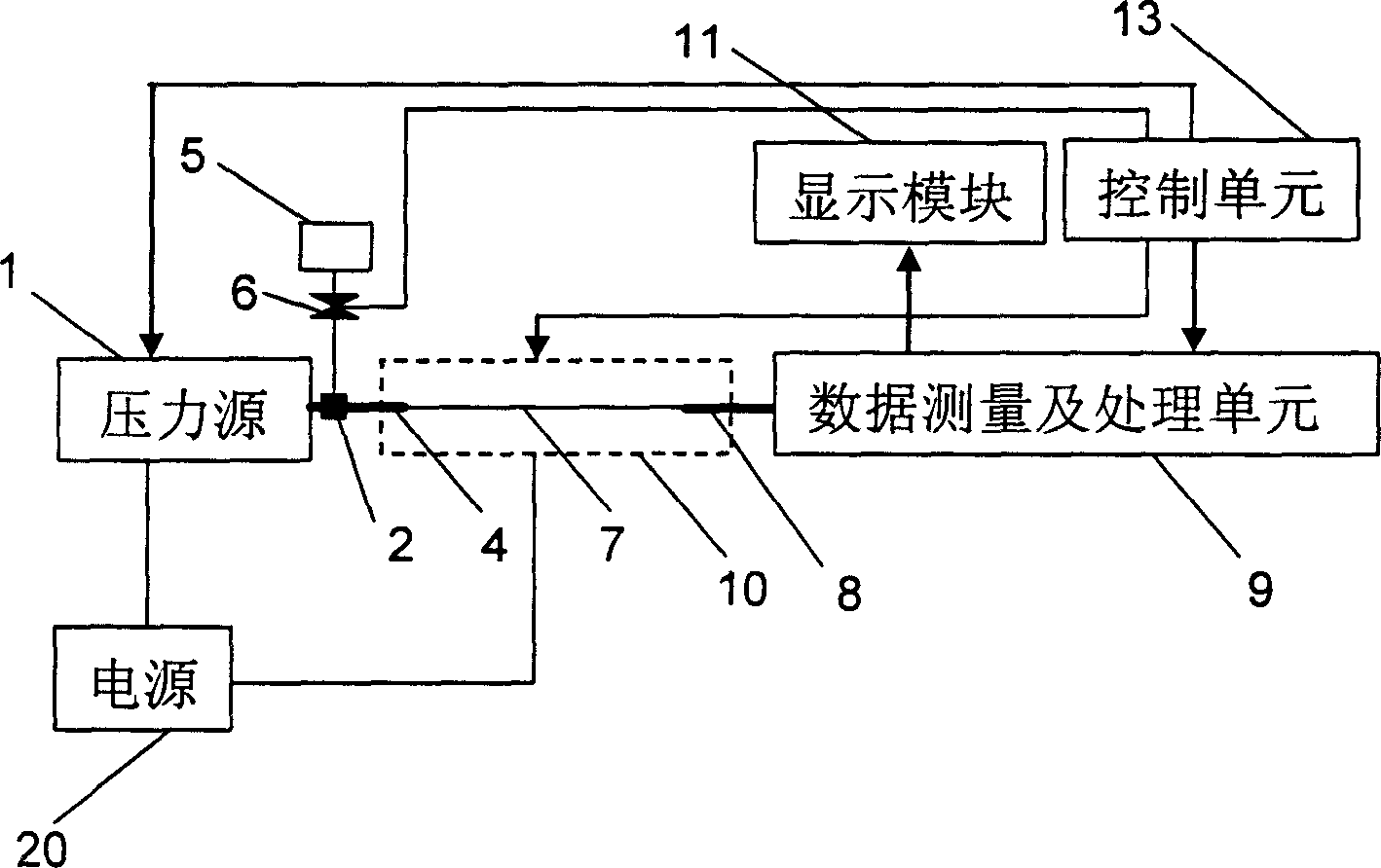
[0039] refer to figure 1 , making an inventive measuring instrument with real-time detection of human blood viscosity, comprising: a power supply 20, a pressure source 1, a tee 2, an infusion tube 4, a valve 6, a calibration liquid container 5 with a calibration liquid, a micron tube 7, A transparent capillary 8 , a temperature control unit 10 , a data measurement and processing unit 9 , a display module 11 and a control unit 13 .

[0040] The pressure source 1 adopts a portable micro-pressure pump available in the market, such as the micro-pump in the Panasonic EW3110 sphygmomanometer.

[0041] The infusion tube 4 adopts an internal diameter of 2 mm and a glass tube of 5 mm in length. One end of the infusion tube 4 communicates with the tee 2 through a sealing rubber ring, and the other end communicates with the micron tube 7 through a sealant.

[0042] Calibration liquid container 5 volume is 2ml, interior calibration liquid, this liquid is 10 -5 The viscosity coefficient of...

Embodiment 2

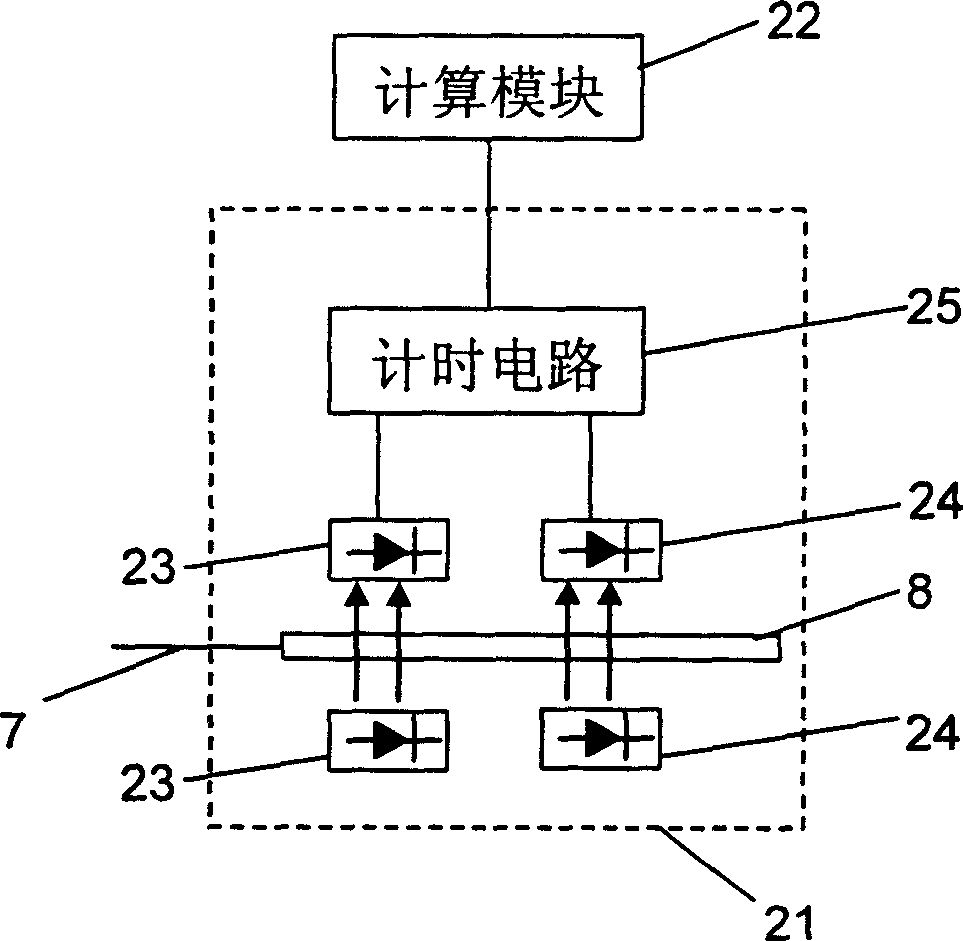
[0063] refer to figure 1 As shown, the infusion tube 4, the micron tube 7 and the transparent capillary 8 in embodiment 1 can also be made into an integral pipeline, wherein the internal diameter parameters of each section are the same as in embodiment 1, and the advantage of being an integral tube like this is that it is convenient to replace .

Embodiment 3

[0065] refer to figure 1 As shown, on the basis of Embodiment 1 or Embodiment 2, the control unit 13 also includes an input module (not shown in the figure), connected with the temperature control unit 10, for setting the control temperature; according to the ambient temperature, it can be Input a temperature value close to the ambient temperature through this module to set the working temperature of the temperature control unit 10, so that the temperature control unit 10 can quickly reach the set working temperature under different ambient temperatures and work stably. The input module of this embodiment can set the value range of the control temperature to be 18 degrees Celsius, 20 degrees Celsius, 22 degrees Celsius, 24 degrees Celsius, 26 degrees Celsius, 28 degrees Celsius, 30 degrees Celsius, 32 degrees Celsius; the data measurement and processing unit 9 is designed as: Store the list of viscosity values ​​of the calibration liquid at the above-mentioned different temper...


PUM

PropertyMeasurementUnit
The inside diameter ofaaaaaaaaaa
Lengthaaaaaaaaaa
The inside diameter ofaaaaaaaaaa

Abstract

The present invention relates to real-time body blood viscosity measuring instrument. The measuring instrument includes pressure source, infusion catheter, micron tube, transparent capillary tube, calibrating liquid container, temperature control unit, data measuring and processing unit, display module and control unit, with the transparent capillary tube being inside data measuring and processing unit. The viscosity measurement has relatively measuring method adopted. The present invention has high detection precision, automatic measurement, small blood consumption of only 20 microliter, disposable infusion catheter, micron tube and transparent capillary tube to avoid cross infection and simple operation, and is portable and suitable for use in hospital and household.

Description

technical field [0001] The invention relates to a measuring instrument for real-time detection of human blood viscosity. Background technique [0002] In the medical field, measuring the viscosity of blood and other physiological fluids is a newly developed diagnostic method, especially for the diagnosis of cardiovascular diseases, cancer, tumors and other difficult diseases. However, the existing medical instruments for detecting blood viscosity are complex in operation and require a large amount of blood sampling. [0003] The existing blood viscosity measurement methods mainly include capillary method, rotation method, falling body method, vibration method, plate method and so on. The simplest method of measurement is the capillary method, the Pinkevitch viscometer. For example: in the Chinese Patent No. 98239308.3, in the document titled "Intelligent Capillary Blood Viscometer", the technical scheme of the viscometer is recorded as follows: there is a glass standpipe, ...

Claims


Application Information

Patent Timeline
IPC IPC(8): G01N33/49G01N11/08
Inventor 李战华覃裕平
Owner INST OF MECHANICS - CHINESE ACAD OF SCI
Why Eureka
Try Eureka