Gas recovery pressure stabilizer

A technology of voltage stabilization device and gas recovery, which is applied in gas collection device, liquid hydrocarbon mixture recovery, petroleum industry, etc., can solve the problems of high operating cost, low exhaust gas volume and high input cost, and achieve low operating cost and good economic benefits. , the effect of low equipment cost

Inactive Publication Date: 2006-10-25
安徽奥生资源利用科技有限公司
View PDF0 Cites 1 Cited by
  • Summary
  • Abstract
  • Description
  • Claims
  • Application Information

AI Technical Summary

Problems solved by technology

Although compression recovery is a relatively mature process, it has high input costs, complex processes, and high operating costs, so the economic benefits ar...

Method used


Image

  • Gas recovery pressure stabilizer

Examples


Embodiment

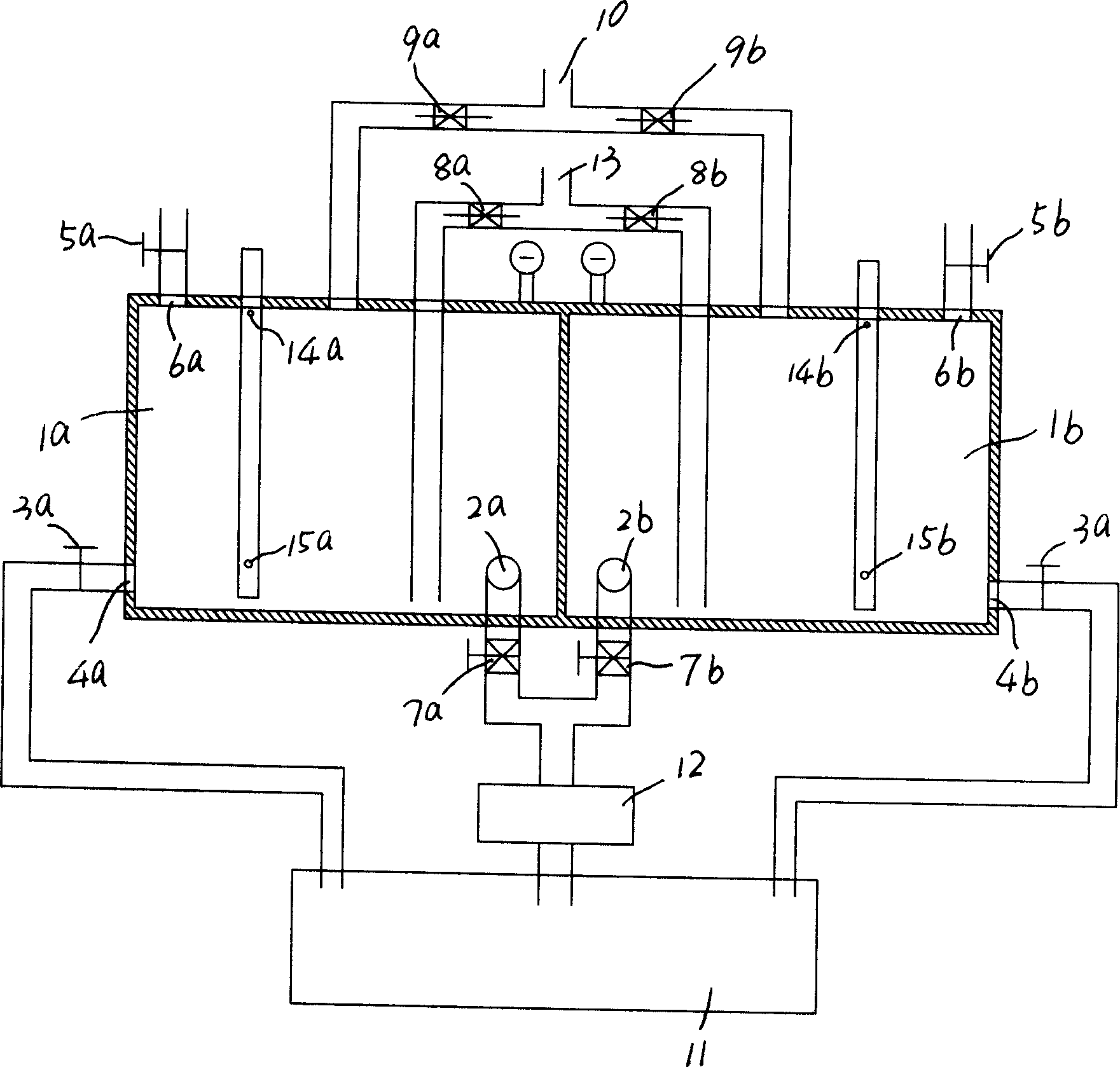
[0019] Referring to Fig. 1, two sets of voltage stabilizing units are provided in this embodiment, and between the two sets of voltage stabilizing units, gas collection and exhaust work in sequence.

[0020] In the specific implementation, the two groups of voltage stabilizing units have the voltage stabilizing chambers 1a and 1b respectively, and the inlets and outlets are respectively set in different parts of the voltage stabilizing chambers 1a and 1b, including:

[0021] Under the sides or bottom of the plenum chamber 1a, 1b, drain pipe ports 4a, 4b with drain valves 3a, 3b are set, and drain valves 5a, 5b are provided on the top of the plenum chamber 1a, 1b. Tracheal openings 6a, 6b;

[0022] The air collecting pipe 13 communicates with the pressure-stabilizing chambers 1a and 1b through the one-way intake valves 8a and 8b respectively, and the pressure-stabilizing exhaust pipe 10 provided with the one-way exhaust valves 9a and 9b communicates with the tops of the pressur...


PUM


Abstract

The invention relates to a gas recycle pressure stabilization device that has a pressure stabilization unit containing pressure stabilization cavity. The outlet, intake and pressurizing pump are set on the different part of pressure stabilization cavity. The invention could effectively take recycling to the unstable system tail gas and supply to gas using device. It is low cost.

Description

Technical field: [0001] The invention relates to a gas pressure stabilizing device. Background technique: [0002] In the production process of some enterprises such as petrochemical industry, some flammable tail gas is often produced. Because the tail gas emission is unstable, that is, large and small, present and absent, it is difficult to use it directly. It must be recycled and stabilized before it can be used as energy to heat objects. Although compression recovery is a relatively mature process, it has high input costs, complex processes, and high operating costs, so the economic benefits are poor and most factories emit less tail gas, so there is not much economic value. If it is discharged directly, it will not only pollute the air, but also be a waste. Invention content: [0003] The purpose of the present invention is to avoid the disadvantages of the above-mentioned prior art, and provide a gas recovery and pressure stabilization device with good voltage stabi...

Claims


Application Information

Patent Timeline
IPC IPC(8): C10G5/00B01L5/02
Inventor 朱恩阔刘春和
Owner 安徽奥生资源利用科技有限公司
Why Eureka
Try Eureka