
Laser feed-back displacement sensor based on frequency locked double-frequency laser

A dual-frequency laser and displacement sensor technology, which is applied in the direction of instruments, optical devices, and measuring devices, can solve problems such as small coherence length, limited distance, and poor coherence, and achieve strong anti-interference ability, large measurement range, and high cost performance Effect

Inactive Publication Date: 2006-10-25
TSINGHUA UNIV
View PDF0 Cites 11 Cited by
  • Summary
  • Abstract
  • Description
  • Claims
  • Application Information

AI Technical Summary

Problems solved by technology

The inclination direction of the sawtooth wave is easy to judge the displacement direction from the senses, but it is not easy to realize on the hardware, and at the medium feedback level, the feedback signal will appear hysteresis, which will bring errors to the counting and seriously affect the accuracy of the system measurement. and linearity
In order to judge the displacement direction, the laser feedback level is required to be weak feedback or medium feedback, and there are requirements for the surface reflection or scattering characteristics of the measured object, or a target mirror is required, but non-contact measurement cannot be realized
At the same time, the requirement for the feedback level also means higher requirements for the collimation of the system. Otherwise, for objects with high reflectivity, due to the incomplete alignment, only a small amount of light is reflected back to the laser resonator, so that the laser works at a very high speed. Weak light feeds back to the horizontal area, causing the laser feedback signal to be in the shape of a cosine wave, and the system cannot realize the direction determination for the symmetrical cosine signal
On the other hand, due to the poor coherence of the semiconductor laser and the small coherence length, the distance between the measured object and the laser feedback measurement system is limited, that is, the laser feedback system using the semiconductor laser as the light source cannot detect the distant target object. Take displacement measurements
These problems limit the application development of the laser feedback displacement measurement system using the semiconductor laser as the light source

Method used


Image

  • Laser feed-back displacement sensor based on frequency locked double-frequency laser
  • Laser feed-back displacement sensor based on frequency locked double-frequency laser
  • Laser feed-back displacement sensor based on frequency locked double-frequency laser

Examples


Embodiment Construction

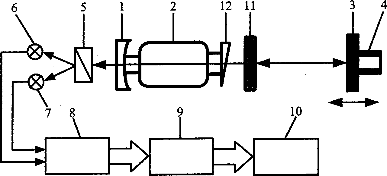
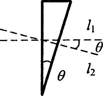
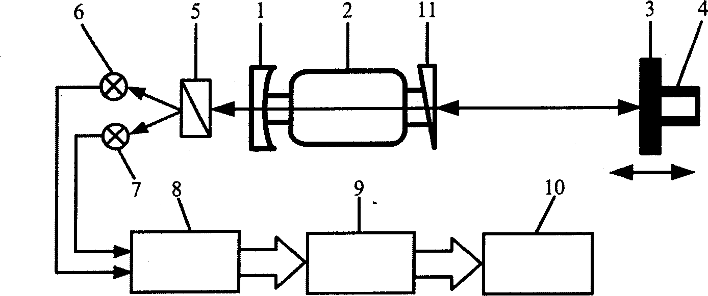
[0028] The invention provides a displacement sensor that can identify the moving direction of the measured object, has a large measurement range, strong anti-interference ability, and high cost performance. Its characteristic is to fix a quartz crystal wedge with a certain wedge angle in the laser cavity to form a frequency-locked dual-frequency laser that can only output one frequency, and use this laser to form a laser feedback system with external reflection or scattering objects to measure the external measured the displacement of the object. When the measured object moves along the laser axis by half the wavelength of the light, the light intensity of the laser changes by one fringe, that is, the system resolution is one-half of the light wavelength, and the light intensity fluctuation cycle of the laser feedback system can be counted directly. Obtain the displacement of the object moving; when the moving direction of the measured object changes, the original oscillating ...


PUM


Abstract

The invention relates to a laser feedback location sensor based on frequency lock two-frequency laser. Putting the quartz crystal with 0-2.9 degree wedge angle is fixed in the cavity of laser to form frequency lock two-frequency laser. It uses the laser and the reflecting or dispersion object to form laser feedback system to measuring the displacement. The invention has simple and tight structure, high measuring accuracy, low cost and has large measuring range.

Description

technical field [0001] The invention belongs to the technical field of laser displacement measurement. Background technique [0002] Laser displacement sensors are widely used in the field of industrial measurement and metrology. Among them, displacement sensors based on interference phenomena, such as interferometric optical fiber displacement sensors and laser interferometers, have the characteristics of large measurement range, high precision, and good linearity. They can be applied It is used in many occasions that require high measurement accuracy. However, this type of system has a very complex structure, large volume, is not easy to carry, has high requirements for collimation, high precision requirements for each component, is difficult to maintain, and the entire system is expensive. Compared with the traditional laser interferometer, the laser feedback interferometer that has emerged in recent years has the advantages of simple structure, compactness, easy alignme...

Claims


Application Information

Patent Timeline
IPC IPC(8): G01B11/02
Inventor 张书练毛威
Owner TSINGHUA UNIV
Learn More