Modularized scanning probe microscope

A technology of scanning probe and microscope, which is applied in the field of scanning probe microscope, can solve the problems of weak observation light, reducing the contrast of scanning image, unable to reduce the cost of the instrument, etc., and achieve the effect of reducing cost and high resonance frequency

Inactive Publication Date: 2006-11-15
SHANGHAI INST OF OPTICS & FINE MECHANICS CHINESE ACAD OF SCI
View PDF1 Cites 18 Cited by
  • Summary
  • Abstract
  • Description
  • Claims
  • Application Information

AI Technical Summary

Problems solved by technology

[0004] 1. The simple combination of an inverted microscope and a scanning probe microscope can only complete the original basic functions of the two, and cannot perform special work according to different needs, and cannot reduce the cost of the instrument
[0005] 2. This technology does not have an independent rough approximation mechanism, and it is inconvenient to realize AFM and SNOM functions on the same rough approximation device by simply replacing the needle tip of the head, and then realize other functions based on SPM, such as laser confocal microscope detection, and Probe-based or microscope-based operations and processing, etc.
[0006] 3. The XYZ three directions of the sample table cannot be scanned, and the selection of the area to be scanned at the micron level cannot be realized. Due to the way of scanning the sample with the probe, it is not conducive to the accurate coincidence of the needle tip and the illumination spot, which reduces the contrast of the scanned image.
[0007] 4. During fluorescence observation, the illumination light is not directly irradiated on the sample after being converged by the lens system, but the light transmitted through the sample by the unreflected part of the end of the micro-cantilever probe enters the objective lens, so that the entire field of view cannot be uniformly illuminated, and Viewing light is very weak, so fluorescence imaging is not ideal

Method used


Image

  • Modularized scanning probe microscope
  • Modularized scanning probe microscope
  • Modularized scanning probe microscope

Examples


Embodiment 1

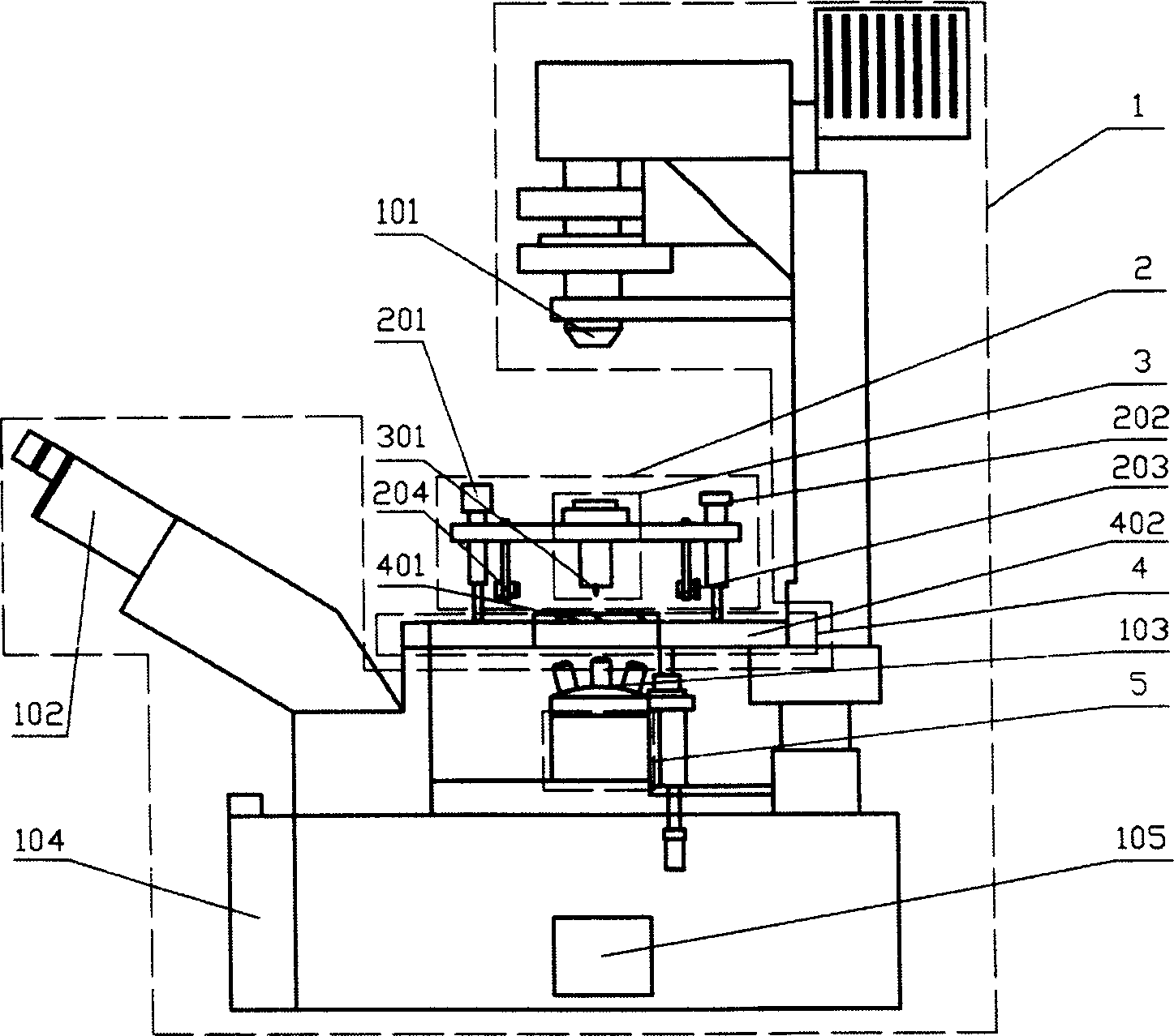
[0038] The principle schematic diagram of embodiment 1 is as Figure 5 As shown, the first module 1, the fourth module 4, and the fifth module 5 are combined. The first module 1 uses Nikon’s TE2000 universal biological microscope for research. This microscope has multi-port output design, ultra-precise Z-axis direction control and NIKON’s unique CFI60 optical system, and is equipped with new motorized accessories. Optional light sources and other accessories can be added to the far light path. The stray light elimination mechanism effectively blocks stray light and eliminates the influence of the surrounding temperature on the microscope prism, and has high anti-vibration performance. The fourth module 4 is a scanner 402 in xyz direction using P-733.3DD device of PI Company, the scanning range is 30×30×10 μm, the center of the device is a 50×50 cm light hole, and the no-load resonance frequency is 1200 Hz. The sample is placed on the transparent sample stage of the fourth mod...

Embodiment 2

[0040] Embodiment 2 is a scanning near-field optical microscope, the principle schematic diagram is as Figure 6 As shown, the first module, the second module, the third module are used to scan the scanning head of the near-field optical microscope, and the fourth module is combined. The stepping motor 201 of the second module 2 adopts M-235.5DG of PI Company, and its one-way repeatability accuracy is 100nm; the lighting LED is fixed on the second module 2, and is adjusted to irradiate the probe tip at a certain angle. The third module 3 is fixed on the second module 2, and the probe tip 301 is perpendicular to the surface of the sample. When working, the first module 1 completes the real-time observation of the needle tip and the sample at the micron level, the second module 2 completes the rough approximation, and the fourth module 4 completes the fine approximation and performs feedback tasks, and at the same time completes the scanning function.

Embodiment 3

[0042] The principle schematic diagram of embodiment 3 is as Figure 7 As shown, the first module, the second module, the third module scanning near-field optical microscope scanning head, and the fourth module are combined. The scanning near-field optical microscope scanning head includes a micro-cantilever probe tip 302, a first lens 303, the first reflector 304, the second reflector 305 and the second lens 306 place the sample on the transparent sample stage of the fourth module 4, and the third module 3 is driven by the second module 2 to roughly approximate the sample, and the fourth module 4 The X, Y, and Z three-dimensional flatbed scanners of module 4 approach and scan the sample in fine detail, thus forming an atomic force microscope for scanning the tip of the sample. The transmissive type illuminated below, because the scanner of module four has a light aperture.


PUM


Abstract

The present invention relates to a modular scanning probe microscope combined with inverted fluorescence microscope. It is formed from five modules, in which the first module is inverted fluorescence microscope, second module is three-jaw approaching device, third module is scanning head, fourth module includes transparent sample table and X, Y and Z three-dimensional scanner and fifth module is laser microscopic extension module. Said invention also provides its working principle and concrete operation method.

Description

technical field [0001] The invention relates to a scanning probe microscope, in particular to a modular scanning probe microscope combined with a fluorescent inverted microscope. Background technique [0002] Scanning probe microscope (hereinafter referred to as SPM) is a surface measurement instrument with ultra-high spatial resolution, which is easy to use and can be used for nanometer detection, manipulation and processing. Most of the existing scanning probe microscopes adopt a fixed structure, so they are only suitable for some specific applications, such as some are only suitable for small sample scanning, and some are only suitable for opaque sample detection. The combination of SPM, fluorescent inverted microscope and three-dimensional scanning sample stage can accurately locate the target to be scanned on the sample and the position of the needle tip. The method of scanning the needle tip of the sample can ensure the high coincidence of the needle tip and the illumi...

Claims


Application Information

Patent Timeline
Patent Type & Authority Applications(China)
IPC IPC(8): G02B21/00G01Q60/02
Inventor 赵虹霞徐文东
Owner SHANGHAI INST OF OPTICS & FINE MECHANICS CHINESE ACAD OF SCI
Why Eureka
Try Eureka