Superconductive energy storage system

A technology of superconducting energy storage and superconducting magnets, which is applied to the system of storing electric energy, the usage of superconductor elements, and electrical components, etc., which can solve the problems of ineffective suppression of harmonics, influence on inverter stability, and high frequency of switching tubes. problem, to achieve the effect of flexible and adjustable charging and discharging voltage, simple and compact structure, and high power density

Inactive Publication Date: 2006-12-06
INST OF ELECTRICAL ENG CHINESE ACAD OF SCI
View PDF3 Cites 6 Cited by
  • Summary
  • Abstract
  • Description
  • Claims
  • Application Information

AI Technical Summary

Problems solved by technology

The problem is that not only two sets of equipment are needed for charging and discharging, but also the capacity of the charging equipment is very large if it is necessary to keep the magnet current constant and to complete the fast charging function, such as US Patent 6,157,094 "Superconducting magnet and its power supply device"; , figure 1 US2002 / 0030952 "Superconducting Magnet Discharge Method and Device" shown in the specific structure diagram, 10 and 11 are the magnet part, 19 is the magnet charging power supply, and other parts are the discharge part, that is, the chopper, which will replace the superconducting magnet. Convert current directly to voltage
In order to meet the requirements of high power, this will inevitably require the capacity of the switch tube to be very large, and even require the switch tube to be connected in series and parallel, which will inevitably affect the stability of the inverter and is not conducive to maintenance.
Moreover, since in the case of high power, the frequency of the switching tube cannot be very high, so the harmonics cannot be effectively suppressed.

Method used


Image

  • Superconductive energy storage system
  • Superconductive energy storage system
  • Superconductive energy storage system

Examples


Embodiment Construction

[0028] The present invention will be further described below in conjunction with the accompanying drawings and specific embodiments.

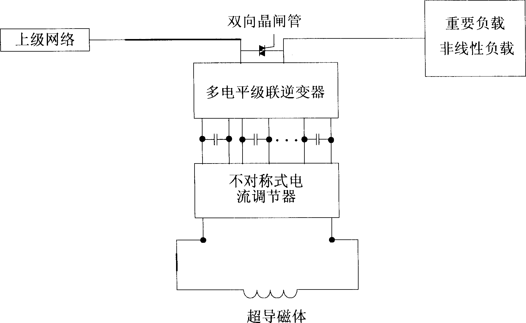
[0029] Such as figure 2 As shown, the outlet of the multi-level cascaded inverter is connected in parallel with the bidirectional thyristor and then connected in series with the power grid. The current side of the asymmetric current regulator is connected in series with the superconducting magnet and the AC / DC charging circuit, and its multiple voltage outlets are directly connected to the input terminals of the cascaded inverter. The asymmetric current regulator can both charge and discharge the superconducting magnet. Since the asymmetric current regulator can charge and discharge, the AC / DC charging circuit can be added or not. One end of the output of the multi-level cascaded inverter is connected to the upper network, and the other end is connected to the nonlinear load.

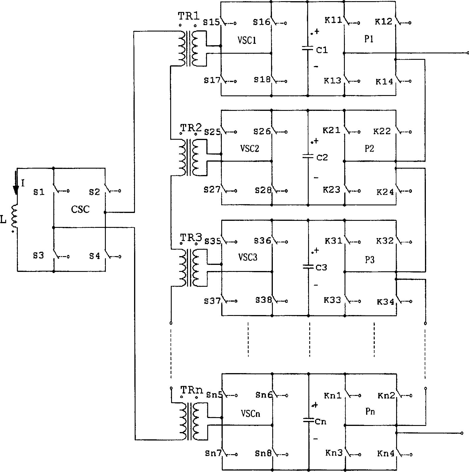
[0030] image 3Shown is the main circuit diagram of the presen...


PUM


Abstract

The energy storage system includes multilevel tandem type inverter, asymmetry type current regulator, superconductive magnet, and control system. The magnet is connected to current source inverter of the current regulator. DC output ends of multiple voltage source inverters of the current regulator are connected to DC input ends of multiple inversion units of multilevel inverter. After being connected to bidirectional thyristor, exit at AC side of the multilevel type inverter is connected to electrical network. The current regulator converts large current in superconductive magnet to steady DC voltage to supply DC end of inverter, and the AC end of the inverter is connected to electrical network. Voltage unit of the current regulator is in mode of phase shift control. Switch off at zero current is realized in phase change of current. Phase shift SPWM mode is adopted for switch control. Features are: reducing switching loss, and prolonging service life of switch tube.

Description

technical field [0001] The invention relates to a superconducting energy storage circuit of a transmission and distribution network. Background technique [0002] Due to the particularity of electric energy itself, the power system has always lacked energy storage and power control links. With the development of large-scale systems and the requirements of the power market, power systems increasingly need links that can be flexibly controlled. The current energy storage methods mainly include battery energy storage, supercapacitor energy storage and pumped hydro storage. The charging and discharging speed of battery energy storage is slow, cannot meet the instantaneous high power exchange, and has environmental pollution problems; the energy storage capacity of supercapacitor is small, and the number of charge and discharge times is limited; pumped energy storage is limited by the environment, and its efficiency is too low. Superconducting energy storage has high energy sto...

Claims


Application Information

Patent Timeline
Patent Type & Authority Applications(China)
IPC IPC(8): H02J15/00
CPCY02E40/67Y02E40/60
Inventor 赵彩宏郭文勇李学斌肖立业林良真余运佳
Owner INST OF ELECTRICAL ENG CHINESE ACAD OF SCI
Why Eureka
Try Eureka