Induction heating device

An electromagnetic induction heating and heating coil technology, applied in the direction of induction heating device, induction heating, induction heating control, etc., can solve the loss of magnetic cooking utensils, the deterioration of noise characteristics, the great change of the open circuit current of semiconductor switching elements, and the non-magnetic Deterioration of cooking utensils, etc.

Inactive Publication Date: 2006-12-06
HITACHI HOME & LIFE SOLUTIONS INC
View PDF1 Cites 19 Cited by
  • Summary
  • Abstract
  • Description
  • Claims
  • Application Information

AI Technical Summary

Problems solved by technology

[0003] However, in the case of heating a non-magnetic cooking utensil and a magnetic cooking utensil with the same heating coil, since there is a large difference in the current flowing through the heating coil in the non-magnetic cooking utensil and the magnetic cooking utensil, the cut-off current of the semiconductor switching element The change is large, and the switching loss increases
In addition, in the case of operating the half bridge, one of the lower arm switching elements is always in the on state, and the loss increases.
In addition, in the method of reducing switching loss by connecting snubber capacitors at both ends of the switching element, if the capacitance of the snubber capacitor is designed to meet the characteristics of the magnetic cooker, the loss and noise characteristics of the non-magnetic cooker will deteriorate. On the contrary, if it is designed in accordance with the non-magnetic cooking utensils, the characteristics of loss and noise in the magnetic cooking utensils will be deteriorated.

Method used


Image

  • Induction heating device
  • Induction heating device
  • Induction heating device

Examples


Embodiment 1

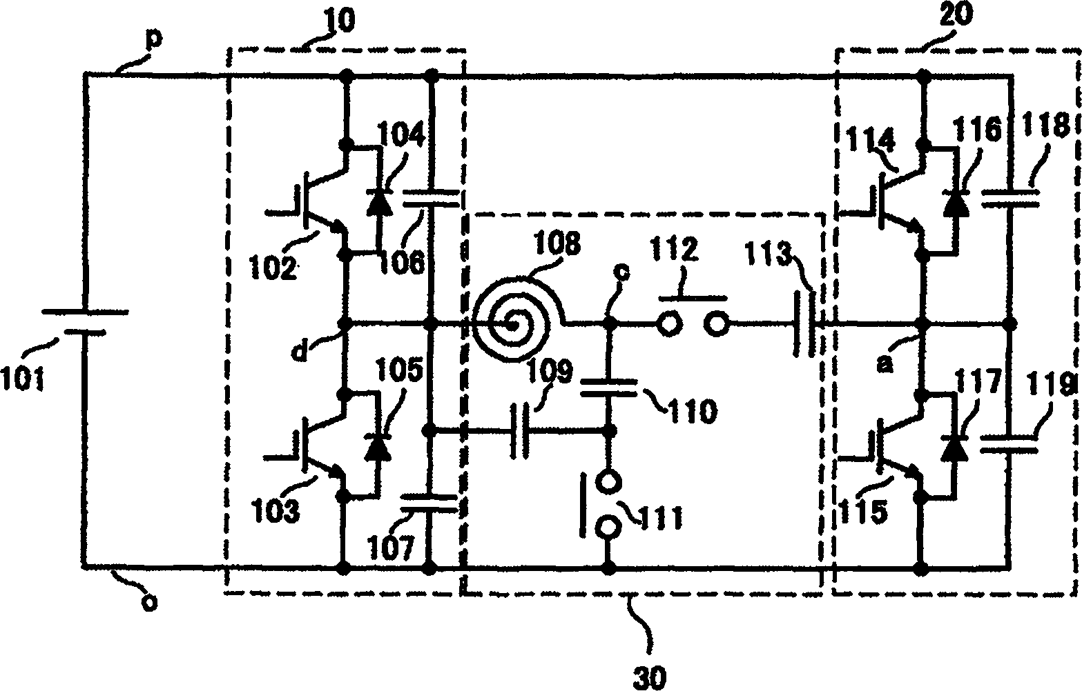
[0022] figure 1 It is a circuit configuration diagram of the induction heating device of this embodiment. exist figure 1 In the power supply circuit 101, between the point p on the positive electrode side and the point o on the negative electrode side, the upper and lower branches 10 connecting the power semiconductor switching elements, that is, IGBT102 and IGBT103 in series, and the upper and lower branches 10 connecting IGBT114 and IGBT115 in series are connected. Upper and lower branches 20. Diodes 104, 105 and diodes 116, 117 are connected in antiparallel to IGBT102, IGBT103, IGBT114, and IGBT115, respectively, and snubber capacitors 106, 107 and snubber capacitors 118, 119 are connected in parallel to each IGBT, respectively. Snubber capacitors 106 , 107 and snubber capacitors 118 , 119 are charged or discharged by the off-circuit current when IGBT102 , IGBT103 , IGBT114 , and IGBT115 are turned off. Since the capacitance of snubber capacitors 106, 107 and snubber cap...

Embodiment 2

[0051] Figure 5 It is a circuit configuration diagram of the induction heating device of this embodiment. exist Figure 5 in, for with figure 1 The same symbols are attached to the same constituent elements. Figure 5 In the point that the power supply circuits 101, 501 are provided in the upper and lower branches 10 and 20 respectively figure 1 different.

[0052] Between the point p on the positive electrode side and the point o on the negative electrode side of the power supply circuit 101 is connected a power semiconductor switching element, that is, an upper and lower branch 10 in which IGBT102 and IGBT103 are connected in series. On the other hand, another power supply circuit 501 is similarly connected to the upper and lower arms 20 in which IGBT114 and IGBT115 are connected in series. Diodes 104, 105 and diodes 116, 117 are connected in antiparallel to IGBT102, IGBT103, IGBT114, and IGBT115, respectively, and snubber capacitors 106, 107 and snubber capacitors 118...

Embodiment 3

[0055] Image 6 It is a circuit configuration diagram of the electromagnetic induction heating device of this embodiment. exist Image 6 In this example, a commercial AC power supply 603 is applied to a diode rectification circuit 604 and full-wave rectified, and then smoothed by an inductor 605 and a capacitor 606 to convert it into a DC voltage. For the power supply circuit 601, since the capacitance of the capacitor 606 is small, it is not completely smoothed, so the input current of the commercial AC power supply 603 is close to a sine wave, reducing high-order waves. In this example, if Figure 7 As shown in , since the DC voltage varies from 0 to the peak voltage of the commercial AC power supply 603, when heating an iron object to be heated, if the upper and lower branches 617 are driven, the unillustrated heating coil of the resonant load circuit 618 A resonant current that varies from 0 to the peak value flows in the middle. On the other hand, when heating an obje...


PUM


Abstract

The invention a magnetoelectric induction heating device which comprises a harmonic oscillation loading circuit including subjects to be heated for converting direct current voltage into alternative current voltage to provide power to the oscillation loading circuit; and a power source circuit for generating direct current voltage. The inverter comprise at least two semi-conductor switch elements connected in series to form up-down branches; a buffer capacity switching unit for switching buffer capacity according to the material of objects to be heated, and a oscillation capacity switching unit for switching oscillating capacity according to the material of the objects to be heated.

Description

technical field [0001] The present invention relates to an induction heating device capable of heating metal cooking utensils of different materials with high efficiency and low noise. Background technique [0002] Generally, an induction heating device uses a half-bridge inverter in which upper and lower arms are formed by two semiconductor switching elements. However, in recent years, as Patent Document 1 (Japanese Unexamined Publication No. 5-251172 ( figure 1 , figure 2 and (0014) paragraph records. )) In order to correspond to metals of all materials, a circuit that can be switched between a half-bridge inverter and a full-bridge inverter according to the material is used. [0003] However, in the case of heating a non-magnetic cooking utensil and a magnetic cooking utensil with the same heating coil, since there is a large difference in the current flowing through the heating coil in the non-magnetic cooking utensil and the magnetic cooking utensil, the cut-off cur...

Claims


Application Information

Patent Timeline
Patent Type & Authority Applications(China)
IPC IPC(8): H05B6/12H05B6/06H05B6/04
CPCY02B40/123Y02B40/00
Inventor 宇留野纯平庄司浩幸神长保男叶田玲彦磯贝雅之岛田直
Owner HITACHI HOME & LIFE SOLUTIONS INC
Why Eureka
Try Eureka