Continuous water separation device

A separation device and container technology, applied in laboratory utensils, laboratory containers, chemical instruments and methods, etc., can solve the problems of low water separation efficiency, short residence time, difficult two-phase separation, etc. Increased productivity and improved separation

Inactive Publication Date: 2006-12-20
NANJING UNIV
View PDF1 Cites 1 Cited by
  • Summary
  • Abstract
  • Description
  • Claims
  • Application Information

AI Technical Summary

Problems solved by technology

[0004] The continuous water separation device involved in the present invention overcomes the serious back-mixing phenomenon existing in the existing device, short residence time in the separation process, difficulty in two-phase separation, and thus low water separation efficiency, and can eliminate the back-mixing phenomenon and prolong the separation residence time. Time, effectively improve the separation, improve the efficiency of water separation

Method used


Image

  • Continuous water separation device
  • Continuous water separation device
  • Continuous water separation device

Examples


Embodiment 1

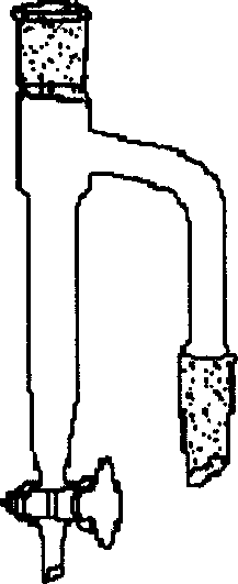
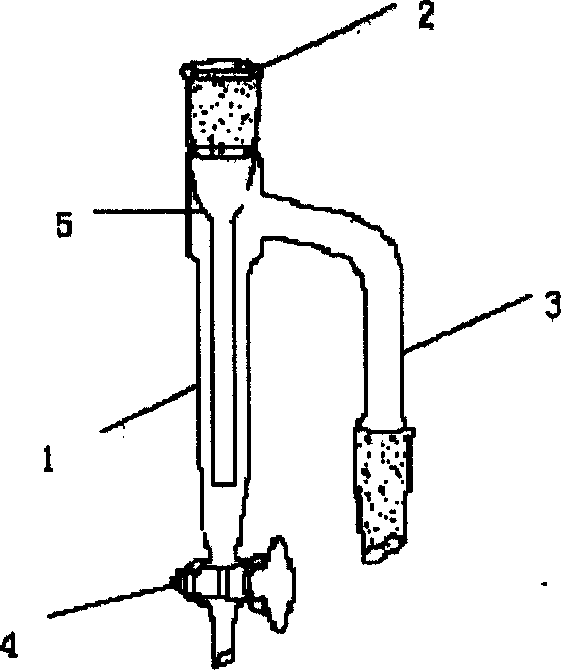
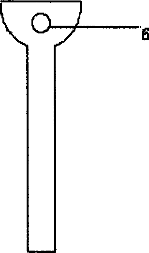
[0020] Such as figure 2 As shown, a continuous water separation device used in the laboratory, including a liquid inlet 2 with a standard grinding port, a container 1, an overflow pipe 3 with a standard grinding port and an outlet valve 4, the liquid inlet 2 and outlet valve 4 are respectively located at the top and bottom of the container 1, and the overflow pipe 3 is located at the upper part of the container 1. A liquid guide tube 5 is installed at the liquid inlet 2 , and the liquid guide tube 5 is inserted into the bottom of the container 1 , and its outlet is located above the outlet valve 4 . Such as image 3 As shown, a pressure balance hole 6 is opened on the top of the catheter 5 as a gas passage, and its position is higher than the liquid level of the container 1 . The water-organic mixed condensate from the condenser continuously enters the bottom of the container 1 from the liquid inlet 2 through the guide pipe 5, and is divided into two phases in the container...

Embodiment 2

[0022] Such as Figure 4 As shown, in the continuous water separation device realized in Embodiment 1 above, an appropriate number of perforated sieve plates 7 are installed in the container 1 , and the perforated sieve plates 7 are located between the overflow pipe 3 and the outlet valve 4 . There are many small holes distributed on the perforated sieve plate 7, such as Figure 5 As shown, as a redistributor, the separation effect of water and organic matter can be significantly improved. Especially when the emulsification phenomenon occurs between water and organic matter, it can overcome the defect that the existing water separation device is difficult to separate.

Embodiment 3

[0024] Such as Figure 6 As shown, in the continuous water separation device realized in the second embodiment above, a condensation jacket 9 is added outside it. The condensing jacket 9 plays a cooling role, which can further reduce the temperature of the mixed condensate in the water separation device, significantly reduce the miscibility of water and organic matter, and thus the separation efficiency can be greatly improved.


PUM


Abstract

The invention relates to a continuous water separator, which comprises: a liquid inlet (2), a container (1), an overflow tube (3), and an outlet valve (4), wherein the liquid inlet (2) and outlet valve (4) are independently on the top and bottom of container (1); the overflow tube (3) is at the upper part of container (1); the liquid inlet (2) is mounted with liquid tube (5) inserted into the lower part of container (1); the upper part of liquid tube (5) has one pressure balance hole (6). The invention can eliminate reflux, prolong the separate time, and improve the separate efficiency. And the invention has simple structure and lower cost.

Description

technical field [0001] The invention relates to a continuous water separation device, in particular to a device for efficiently and continuously separating water and organic matter in laboratories or industrial devices in the field of chemical engineering. Background technique [0002] In laboratory research and industrial production in the field of chemistry and chemical engineering, a type of chemical reaction is often involved, and water is formed in the product of this type of chemical reaction. According to the principle of chemical reaction balance, in order to ensure the continuation of the reaction, in order to obtain a suitable reaction rate and a higher conversion rate, during the reaction process, it is necessary to continuously combine the water produced by the reaction with the organic matter of the reactant or solvent. separated from the reaction system. For example, for the common esterification reaction, the condensation reaction between alcohol and acid wil...

Claims


Application Information

Patent Timeline
Patent Type & Authority Applications(China)
IPC IPC(8): B01L3/00
Inventor 芮必胜范晓泉顾浩
Owner NANJING UNIV
Why Eureka
Try Eureka