
Guide float valve tray

A float valve tray and float valve technology, which is applied in the field of fractionation towers, can solve the problems of not fully exerting the gas propelling effect, the liquid flow does not have a guiding effect, and reducing the gas outlet area, etc., so as to increase the mass transfer contact area, reduce the Small resistance, the effect of reducing resistance

Inactive Publication Date: 2004-06-30
NANJING UNIV
View PDF0 Cites 0 Cited by
  • Summary
  • Abstract
  • Description
  • Claims
  • Application Information

AI Technical Summary

Problems solved by technology

One disadvantage of the float valve is that it has no guiding effect on the liquid flow on the tray, resulting in a large gradient of the liquid level on the tray, serious back-mixing of the liquid, and impaired mass transfer efficiency.
This float valve is one of the best guided float valves at present, but it also has disadvantages, that is, the front end of the valve plate is a plate-shaped valve leg, which is like a baffle, so that the gas cannot flow from the front end of the valve plate to the liquid. The flow is ejected in the same direction, the driving effect of the gas under the valve plate is not fully exerted, and the outlet area through which the gas passes is reduced, resulting in a large pressure drop on the plate

Method used


Image

  • Guide float valve tray
  • Guide float valve tray
  • Guide float valve tray

Examples


Embodiment 1

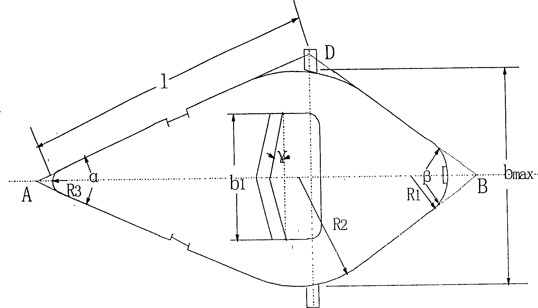
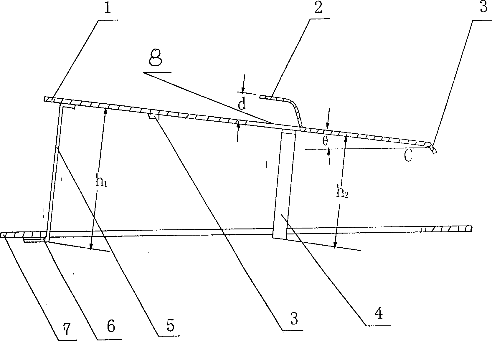
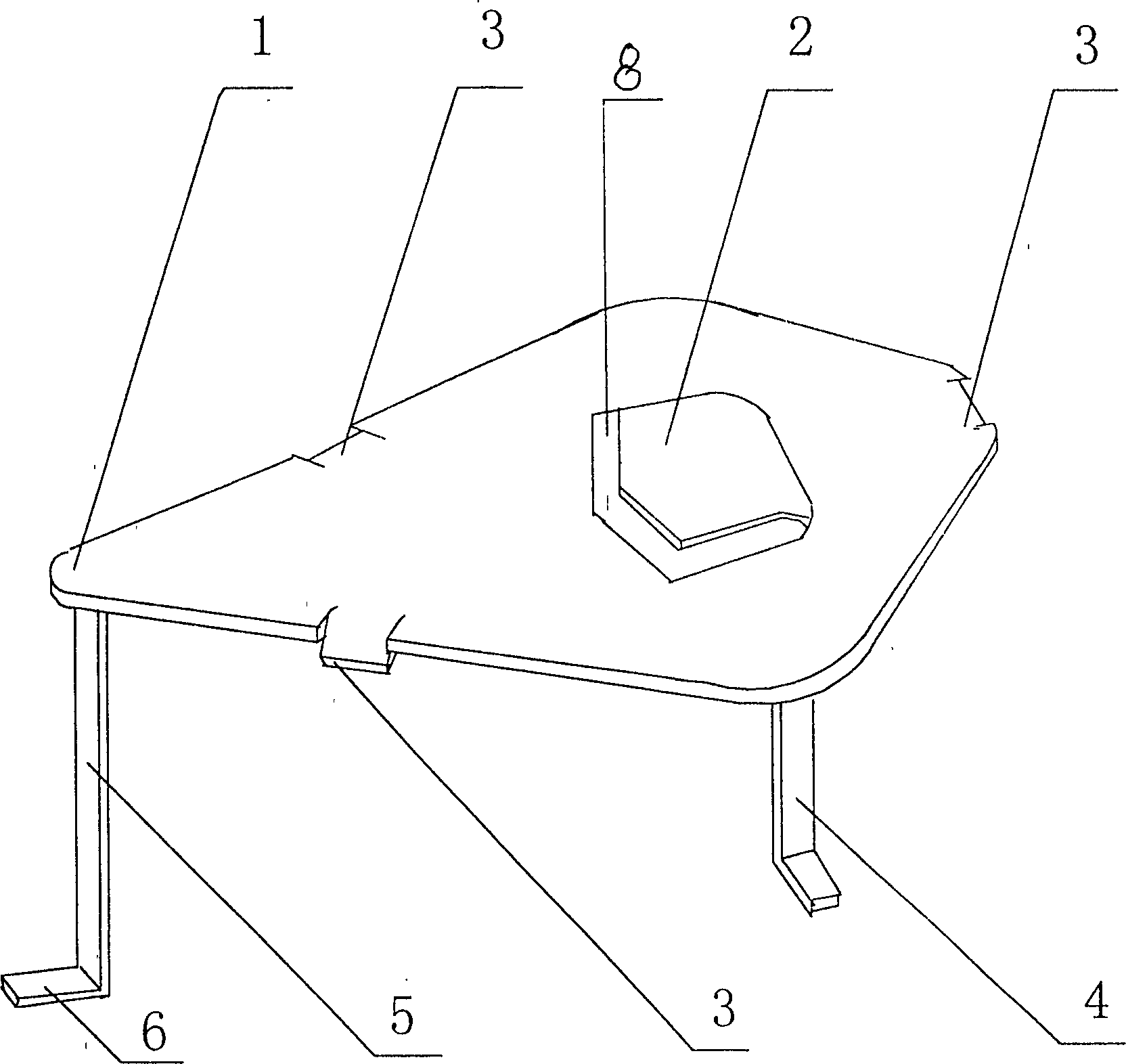
[0021] Propylene oxide-water rectification system adopts the symmetrical quadrilateral guide valve tray of the present invention to transform the original F1 type float valve tray. The valve adopts such as Figure 4 For the fork row method shown in b, the valve center distance S = 220mm, and the distance between the float valve rows t = 150mm. Guided symmetrical quadrilateral float valve such as figure 1 , 2 As shown in and 3, the long side AD of the symmetrical quadrilateral guide valve cover 1 has a length l=70mm, a front angle α=35°, a back angle β=60°, and the radii of the four corner arcs are respectively R 1 = 30mm, R 2 = 50mm, R 3 =10mm, there is a guide hole 8 on the valve cover 1, the guide hole 8 is pentagonal, and its shape is a combination of an isosceles triangle and a rectangle, and the angle between the two waists of the isosceles triangle and the base is γ=15 °, the width of the guide hole b 1 =0.6b, b is the maximum width of the valve cover. A guide pla...

Embodiment 2

[0023] Methane chloride chilling tower, the processing capacity is 20000t / a, the tower diameter is φ1800mm, the original tower is a sieve plate tower, the plate spacing is 500mm, the opening rate is 12%, and the number of trays is 12, due to the unsatisfactory heat transfer effect And adopt guide float valve tray of the present invention, its concrete structure parameter is: plate spacing 500mm, opening ratio 12%, tower diameter is constant, and tray number is constant, and the AD length l=60mm of float valve bonnet 1, Front angle α=30°, rear angle β=57°, R 1 , R 2 , R 3 Respectively 25, 45, 8mm, γ=10°, b 1 =0.5b, the length of the front valve leg 5 is h 1 =38mm, length of rear valve leg h 2 = 25mm, the operation results show that the outlet temperature of the vapor phase at the top of the tower drops from 125°C to 106°C, and the operating flexibility changes from 1.8:1 to 2.4:1 and it can run normally. In addition, the pressure drop of the whole tower is changed from the...


PUM


Abstract

The present invention relates to a guide float valve plate which comprises a guide float valve which is a symmetrical quadrangular guide float valve, its valve cover is a quadrangular from with symmetrical diagonal liens, the included angle of long edges is directed against overflow weir, under the valve cover more than three valve legs are mouthed, front valve leg length is longer than rear valve leg length, so that when the float value is completely opened, between valve cover and valve hole plate an included angle toward overflow weir is opened, said included angle is 2-10 deg, and on the valve cover can be mounted the guide hole and guide plate. Said invention can effectively reduce liquid level gradient on the plate, raise plate flux, raise mass transfer efficiency and reduce resistance of plate.

Description

1. Technical field [0001] The invention relates to a fractionation tower, in particular to a valve tower. 2. Background technology [0002] The valve tray has the advantages of large production capacity, large operating flexibility, and high tray efficiency, and is one of the most widely used plate types. At present, the F1 type float valve is commonly used in industrial float valve trays. One disadvantage of the float valve is that it has no guiding effect on the liquid flow on the tray, resulting in a large gradient of the liquid level on the tray, severe back-mixing of the liquid, and impaired mass transfer efficiency. In addition, due to its structural characteristics, the contact area between the gas phase and the liquid phase rising from the valve plate is relatively small, which also limits its separation efficiency. For this reason, people have made various improvements to it, and have developed guide float valves, trapezoidal float valves, combined float valves, a...

Claims


Application Information

Patent Timeline
Patent Type & Authority Patents(China)
IPC IPC(8): B01D3/18B01D3/24
Inventor 张志炳周政
Owner NANJING UNIV
Learn More