Laser processing of a locally heated target material

A technology of target materials and lasers, which is applied in the field of laser processing of locally heated workpieces, can solve the problems of workpiece production rate limitation, formation of debris and slag, and difficulty in removal

Inactive Publication Date: 2006-12-20
ELECTRO SCI IND INC
View PDF6 Cites 14 Cited by
  • Summary
  • Abstract
  • Description
  • Claims
  • Application Information

AI Technical Summary

Problems solved by technology

However, one disadvantage of laser dicing semiconductor wafers is the formation of chips and dross, both of which adhere to the wafer and are difficult to remove
Another disadvantage of laser cutting semiconductor wafers is that the production rate of workpieces is limited by the power capability of the laser

Method used


Image

  • Laser processing of a locally heated target material
  • Laser processing of a locally heated target material
  • Laser processing of a locally heated target material

Examples


Embodiment Construction

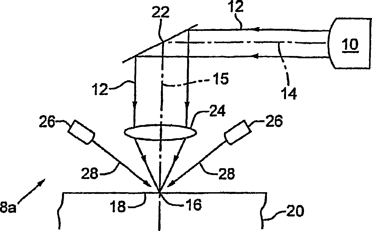
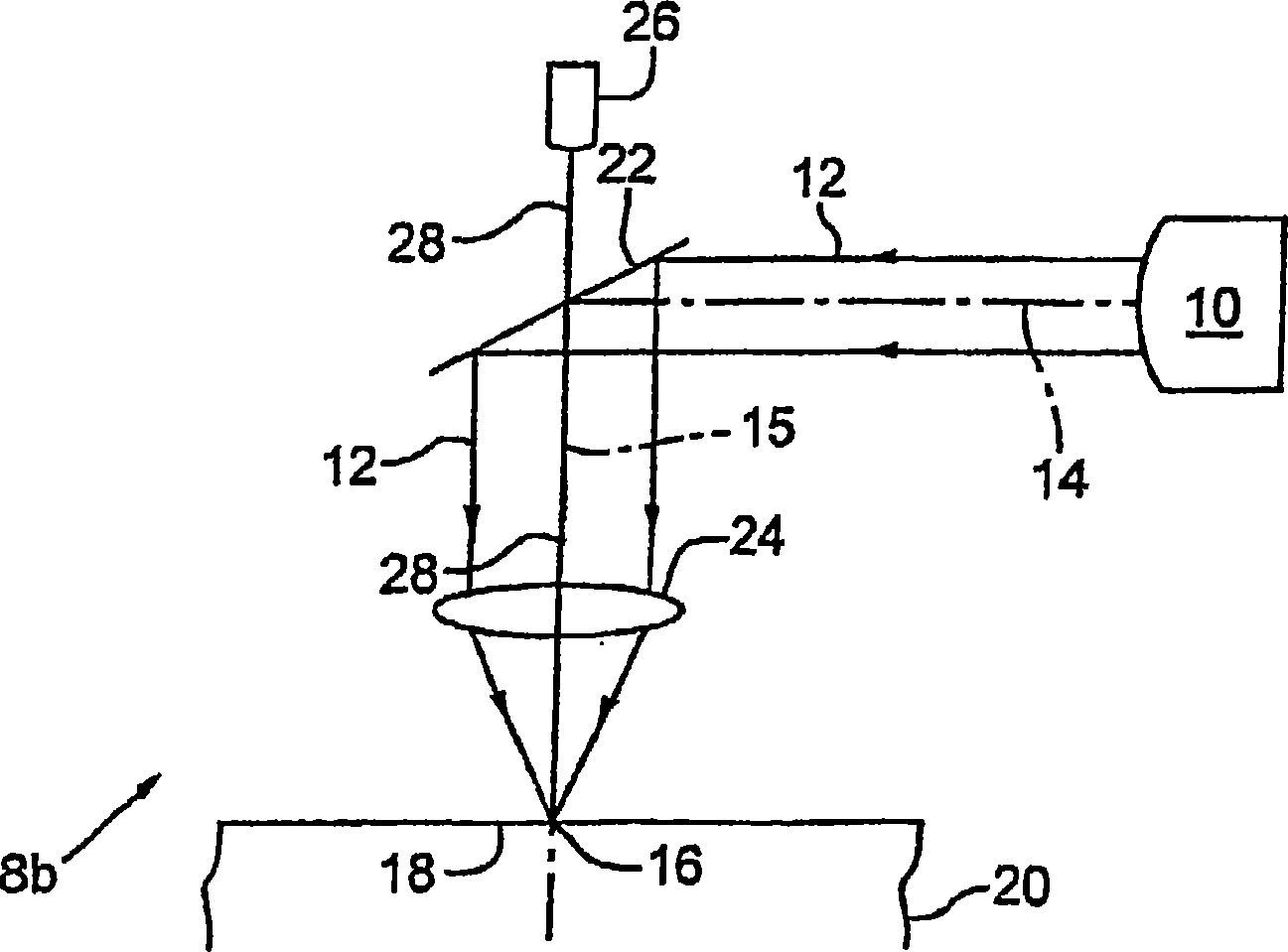
[0028] Figure 1a and 1b are simplified schematic diagrams of two alternative preferred embodiments of laser systems 8a and 8b configured to laser machine workpieces according to the method of the present invention.

[0029] refer to Figure 1a , the processing laser 10 emits an output processing beam 12 that propagates along a first section 14 of an optical axis and a second section 15 of the optical axis, incident on a target material 18 of a workpiece 20 at a target location 16 . Processing beam 12 reflects off mirror 22 and propagates through objective lens 24 which focuses processing beam 12 onto a small spot at target location 16 . The two light sources 26 as heating sources emit a heating beam 28 which travels along separate beam paths at an acute angle with respect to the second section 15 of the optical axis and is incident on the target material 18 at the target location 16 . The heating beam 28 carries thermal energy to the target material 18 to increase its temper...


PUM

PropertyMeasurementUnit
sizeaaaaaaaaaa
frequencyaaaaaaaaaa
frequencyaaaaaaaaaa

Abstract

A method and laser system effect rapid removal of material from a workpiece (20) by applying heating energy in the form of a light beam (28) to a target location (16) on the workpiece to elevate its temperature while maintaining its dimensional stability. When the target portion of the workpiece is heated, a laser beam (12) is directed for incidence on the heated target location. The laser beam preferably has a processing laser output that is appropriate to effect removal of the target material from the workpiece. The combined incidence of the processing laser output and the heating energy on the target location enables the processing laser output to remove a portion of the target material at a material removal rate that is higher than the material removal rate achievable when the target material is not heated.

Description

technical field [0001] The present invention relates to laser machining of locally heated workpieces and, more particularly, to a system and method for increasing the target material removal rate and workpiece production rate by increasing the temperature at the target location on the workpiece. Background technique [0002] Laser machining can be performed on several different workpieces using different lasers for different processes. Specific types of laser machining to be discussed in relation to the present invention are laser machining of single or multilayer workpieces to form apertures and / or holes, and laser machining of semiconductor wafers to singulate the wafer. [0003] With regard to laser machining holes and / or apertures in multilayer workpieces, U.S. Patent Nos. 5,593,606 and 5,841,099 to Owen et al. describe operating an ultraviolet (UV) laser system to generate laser output pulses, characterized in that the laser parameter set enables A via or blind hole in...

Claims


Application Information

Patent Timeline
Patent Type & Authority Applications(China)
IPC IPC(8): B23K26/00B23K26/14B23K26/16B23K26/18B23K26/36
Inventor Y·孙L·金娇R·S·哈里斯P·苏布拉马尼扬R·F·海恩希W·陆
Owner ELECTRO SCI IND INC
Why Eureka
Try Eureka