Circuit device of leakage current detector of lightning protector and its operating method

A leakage current and circuit device technology, applied in the field of circuit devices of leakage current detectors, can solve the problems of non-existence and inability to display the specific value of resistive current, etc.

Inactive Publication Date: 2007-01-10
HOHAI UNIV CHANGZHOU
View PDF2 Cites 9 Cited by
  • Summary
  • Abstract
  • Description
  • Claims
  • Application Information

AI Technical Summary

Problems solved by technology

However, this detection device cannot display the specific value of the resistive current of the leaked full current,

Method used


Image

  • Circuit device of leakage current detector of lightning protector and its operating method
  • Circuit device of leakage current detector of lightning protector and its operating method
  • Circuit device of leakage current detector of lightning protector and its operating method

Examples


Embodiment 1

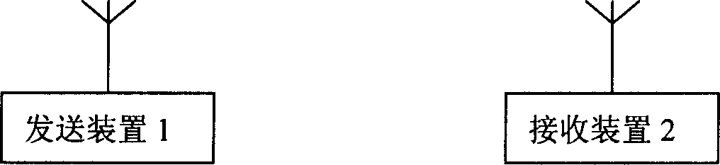
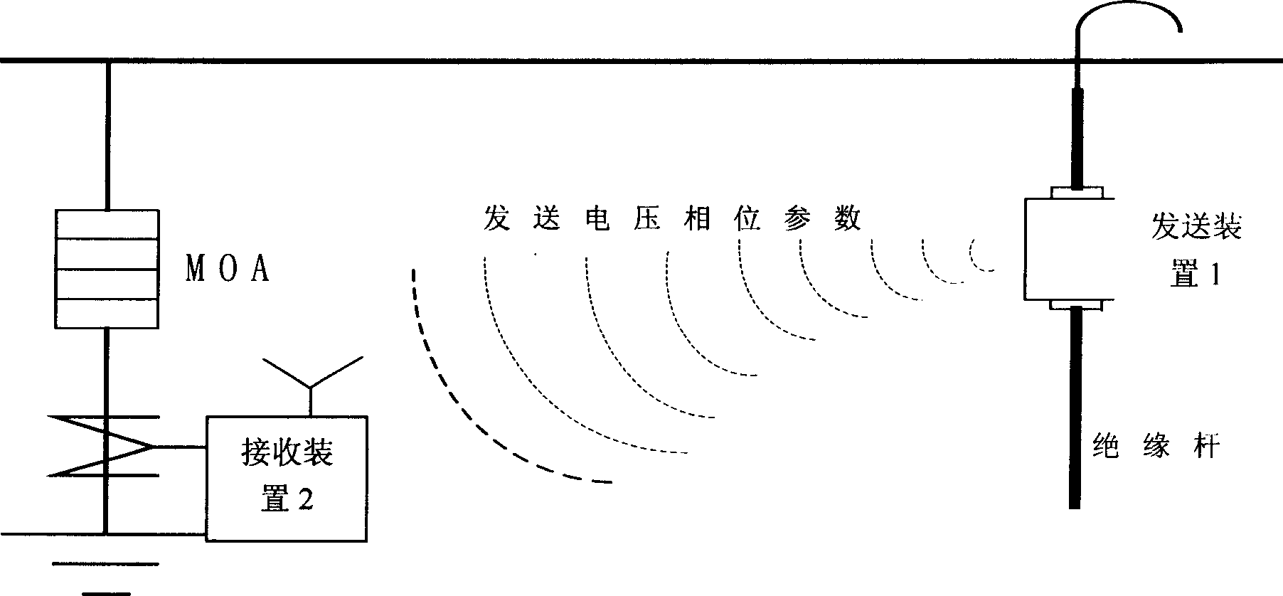
[0037] See figure 1 , The circuit device of the leakage current detector of the lightning arrester of this embodiment has a sending device 1 and a receiving device 2 .

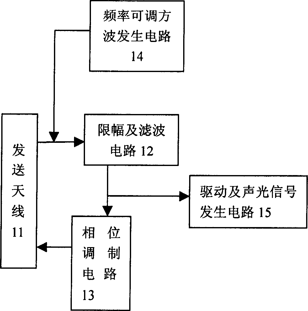
[0038] See image 3The transmitting device 1 has a transmitting antenna 11 , a limiter and filter circuit 12 , a phase modulation circuit 13 , a frequency adjustable square wave generating circuit 14 and a driving and acousto-optic signal generating circuit 15 . The transmitting antenna 11 is an antenna that receives the voltage signal of the high-voltage phase line connected to the arrester to be tested and transmits a high-frequency signal loaded with the voltage phase signal of the high-voltage phase line in the form of wireless transmission. The limiter and filter circuit 12 is used to couple the voltage signal of the high-voltage phase line received by the transmitting antenna 11 through electromagnetic induction, and then use the voltage stabilization method to limit the voltage signal, and filter the l...

Embodiment 2

[0060] The rest of this embodiment is the same as Embodiment 1, except that the ASIC application specific integrated circuit 22 in the receiving device 2 is a complex programmable logic device CPLD with a model number of EP1K100.

Embodiment 3

[0062] See Figure 6 , the rest of this embodiment is the same as Embodiment 1, the difference is that the resistive current detection circuit 20 of the receiving device 2 has an amplification and analog-to-digital conversion circuit 23, an embedded processor 29 and a shaping circuit 26, and the embedded Formula processor 29 replaces the effect of ASIC application-specific integrated circuit 22 and single-chip microcomputer 24 in embodiment 1, and embedded processor 29 in use reverses voltage phase square wave signal and carries out logical operation with current phase square wave signal and obtains The phase difference square wave signal, and the single square wave and period of the phase difference square wave signal are respectively obtained by high-frequency counting to obtain two values, and the two values ​​are divided and then multiplied by a coefficient to obtain the phase difference data. Then calculate the cosine value of the phase difference data, and then multiply ...


PUM


Abstract

The present invention relates to a lightning arrester leakage current circuit device and working method. Said circuit device has receiving equipment connected with ground terminal of tested lightning arrester set between high voltage phase conductors with earth, transmitting device hung on above-mentioned high voltage phase conductors and radio fitted with said receiving equipment, transmitting device transmitting high-frequency signal loaded with high voltage phase conductors voltage phase signal, receiving equipment receiving said signal through radio mode, and receiving connected lightning arrester leakage total current signal through cable mode, through relevant processing to obtain resistance current value in leakage total current signal, finally displaying said current value to user.

Description

technical field [0001] The invention relates to a circuit device of a leakage current detector and a working method thereof. Background technique [0002] A complete set of lightning protection devices should be installed on the high-voltage lines of the power system. Before the high-voltage lines of the power system are sent to the user's own transformer, a lightning arrester should be installed between each phase line of the high-voltage line and the ground. It can also be set on the section of the high-voltage line that passes through the minefield. At present, the surge arrester widely implemented in our country is MOA (English abbreviation of Metal Oxide Arrester). In order to ensure the normal function of MOA, it is necessary to regularly detect the state of MOA. [0003] In the case of normal operation, the MOA operating parameters can be simplified as a non-linear resistor connected in parallel with a constant value capacitor, so the full leakage current I through t...

Claims


Application Information

Patent Timeline
IPC IPC(8): G01R31/02
Inventor 张金波胡钢张学武
Owner HOHAI UNIV CHANGZHOU
Why Eureka
Try Eureka