Fuel cell contact element including a tio2 layer and a conductive layer

A fuel cell and conductive layer technology, applied in fuel cell parts, fuel cells, transportation fuel cell technology, etc., can solve problems such as limiting the long-term durability of the membrane and increasing the ion resistance of the battery

Inactive Publication Date: 2007-01-10
GM GLOBAL TECH OPERATIONS LLC
View PDF3 Cites 13 Cited by
  • Summary
  • Abstract
  • Description
  • Claims
  • Application Information

AI Technical Summary

Problems solved by technology

Dry inlet gas has a drying effect on the membrane which increases the ionic resistance of the cell and limits the long-term durability of the membrane

Method used


Image

  • Fuel cell contact element including a tio2 layer and a conductive layer
  • Fuel cell contact element including a tio2 layer and a conductive layer
  • Fuel cell contact element including a tio2 layer and a conductive layer

Examples


Embodiment Construction

[0018] The following discussion of embodiments of the present invention is directed to a fuel cell bipolar plate that includes a metal oxide layer and a conductive layer to render the bipolar plate conductive, hydrophilic, and stable in the fuel cell environment, for which the bipolar plate The description of the plates is merely exemplary in nature and is in no way intended to limit the invention or the application or use of the invention.

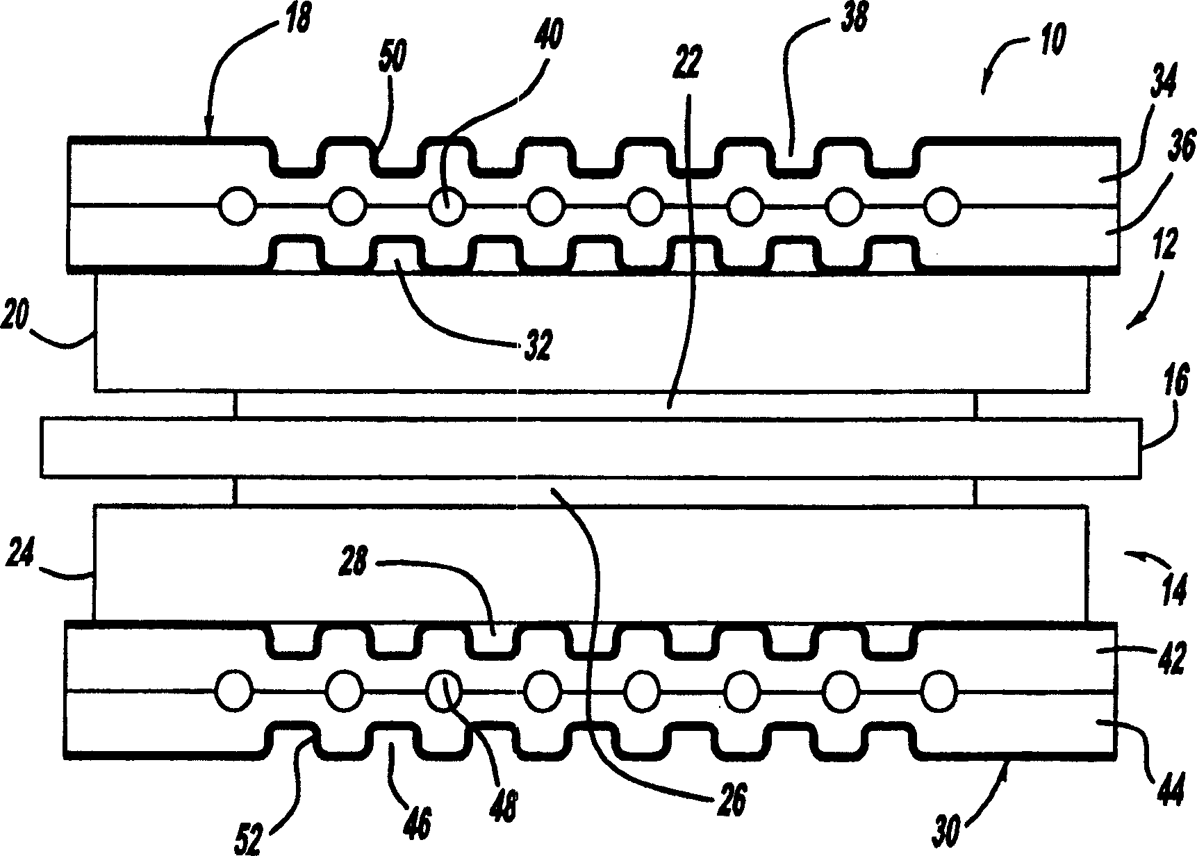
[0019] figure 1 is a cross-sectional view of a fuel cell 10 as part of a fuel cell stack of the type discussed above. Fuel cell 10 includes a cathode side 12 and an anode side 14 separated by a perfluorosulfonic acid membrane 16 . A cathode side diffusion media layer 20 is disposed on the cathode side 12 and a cathode side catalyst layer 22 is disposed between the membrane 16 and the diffusion media layer 20 . Likewise, an anode side diffusion media layer 24 is disposed on the anode side 14 and an anode side catalyst layer 26 is dispose...


PUM

PropertyMeasurementUnit
thicknessaaaaaaaaaa
thicknessaaaaaaaaaa

Abstract

A flow field plate or bipolar plate for a fuel cell that includes a metal oxide coating that makes the bipolar plate conductive, hydrophilic and stable in the fuel cell environment. Non-limiting examples of suitable doped coatings Ta doped TiO2, Nb doped TiO2 and F doped SnO2. In an alternate embodiment, the metal oxide is a non-stoichiometric metal oxide that includes oxygen vacancies in the lattice structure that provides the conductivity. Non-limiting examples of suitable non-stoichiometric metal oxides include TiO2-x and TiO2+y.

Description

technical field [0001] The present invention relates generally to fuel cell bipolar plates, and more particularly to 2 ) layer and conductive layer of the fuel cell bipolar plate, the TiO 2 Layers and conductive layers combine to make the bipolar plate conductive, hydrophilic, and stable in the fuel cell environment. Background technique [0002] Hydrogen is a very attractive fuel because it is clean and can be used to efficiently generate electricity in fuel cells. A hydrogen fuel cell is an electrochemical device that includes an anode and a cathode with an electrolyte placed between the two. The anode receives hydrogen and the cathode receives oxygen or air. Hydrogen dissociates at the anode to produce free protons and electrons. Protons pass through the electrolyte to the cathode. The protons react with oxygen and electrons at the cathode to produce water. Electrons from the anode cannot pass through the electrolyte and thus do work through the load before being se...

Claims


Application Information

Patent Timeline
Patent Type & Authority Applications(China)
IPC IPC(8): H01M8/02H01M4/86
CPCH01M2008/1095H01M2250/20Y02T90/32H01M8/0226H01M8/0206H01M8/0228H01M8/0204Y02E60/50H01M8/021H01M8/04074Y02T90/40
Inventor G·维亚斯M·H·阿布德埃尔哈米德T·A·特拉波尔德Y·M·米克海尔
Owner GM GLOBAL TECH OPERATIONS LLC
Why Eureka
Try Eureka