Electric connector, unit for covering its connected part between two terminals, storage cell and bus bar equipped with them

An electrical connector and battery technology, which is applied to the parts of the connecting device, the two-part connecting device, and the parts of the battery pack, etc., can solve the problems that the connector is smaller than the battery, is not easy to see, and damages the engaging part, etc. Achieve the effect of improving assembly efficiency, simple assembly and disassembly operations, and easy maintenance.

Inactive Publication Date: 2007-01-10
YKK CORP +1
View PDF9 Cites 9 Cited by
  • Summary
  • Abstract
  • Description
  • Claims
  • Application Information

AI Technical Summary

Problems solved by technology

[0016] The above-mentioned existing problems can be solved through the development of such a quick snap-fit ​​electrical connector, but since the connector is smaller than the battery, it is not easy to see clearly during disassembly and assembly, and sometimes the center position of the male and female connector parts is displaced, The engaging part may be damaged, and it is necessary to further improve the operability during engaging
In addition, when dust or liquid adheres to the connector or its terminal connection part, the resistance increases or the conductivity fluctuates, which easily affects the good electrical connection. Therefore, it is also necessary to improve the dustproof and waterproof aspects.

Method used


Image

  • Electric connector, unit for covering its connected part between two terminals, storage cell and bus bar equipped with them
  • Electric connector, unit for covering its connected part between two terminals, storage cell and bus bar equipped with them
  • Electric connector, unit for covering its connected part between two terminals, storage cell and bus bar equipped with them

Examples


Embodiment

[0147] Below, according to the attached Figure 1 While describing various embodiments of the present invention, the present invention will be described in more detail.

[0148] First, refer to figure 1 and figure 2 A basic embodiment of an electrical storage device in which the connector of the present invention can be suitably used will be described.

[0149] This power storage device is, for example, a large capacitor constituted by a plurality of electric double layer capacitor cells (battery batteries), and is used as a supercapacitor of a power storage power supply device of an electric vehicle.

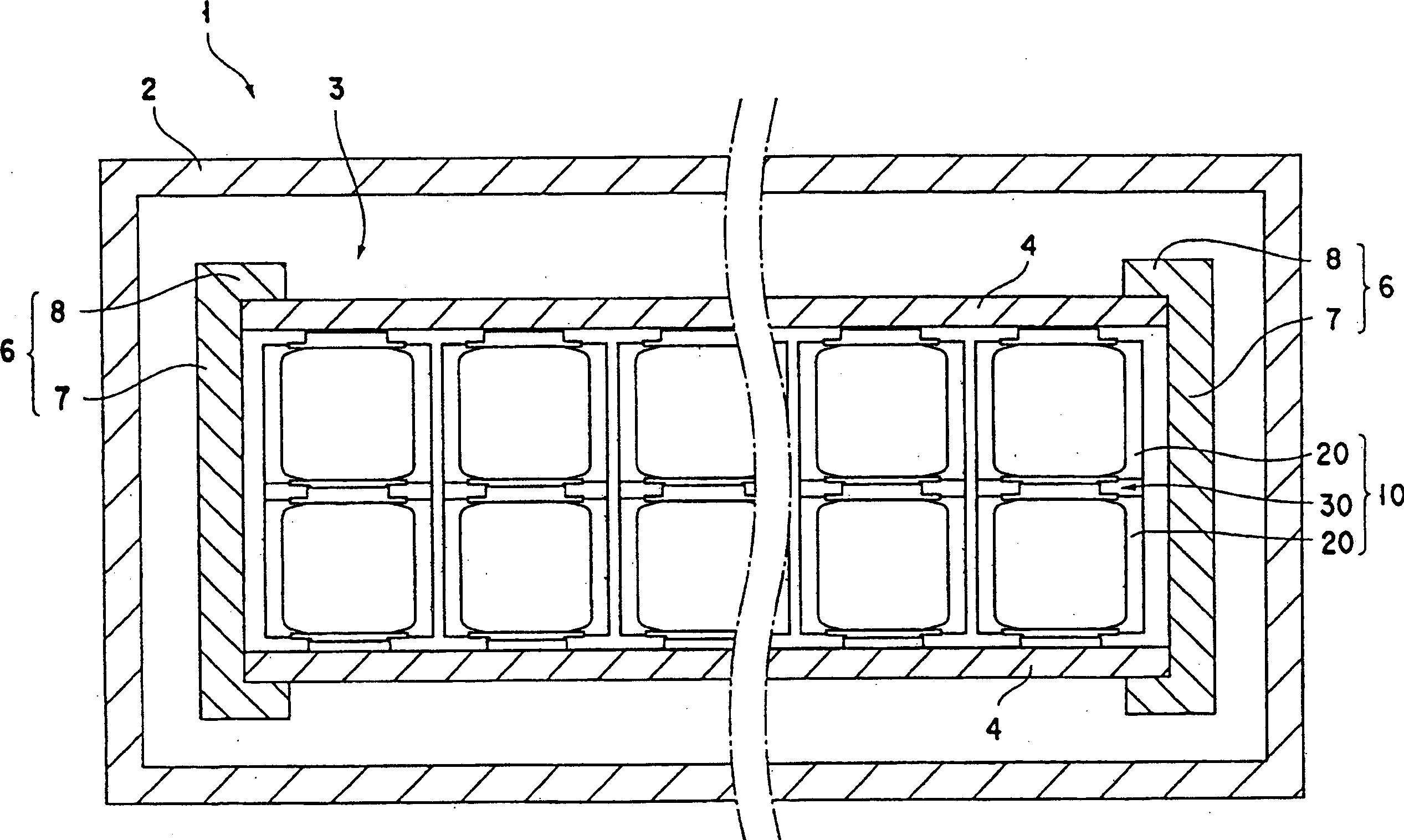
[0150] Such as figure 1 As shown, the power storage device 1 has a frame body 2 and a power storage module 3. The frame body 2 has a storage space inside; the power storage module 3 is housed in the frame body 2 and has a large power storage capacity.

[0151] The storage battery module 3 has a capacitor unit (storage battery) 20, a bus bar 4, a binding plate (enclosed wit...

Deformed example 1

[0192] Refer to the following Figure 9 Modification 1 of the connector of the present invention will be described.

[0193] The basic structure of Modification 1 is the same as that of the connector 30 described in the first embodiment, but this Modification 1 is characterized by the female thread portion provided on the inner ring portion. In the following description, although the male connector part is used as an example, it is also applicable to the female connector part.

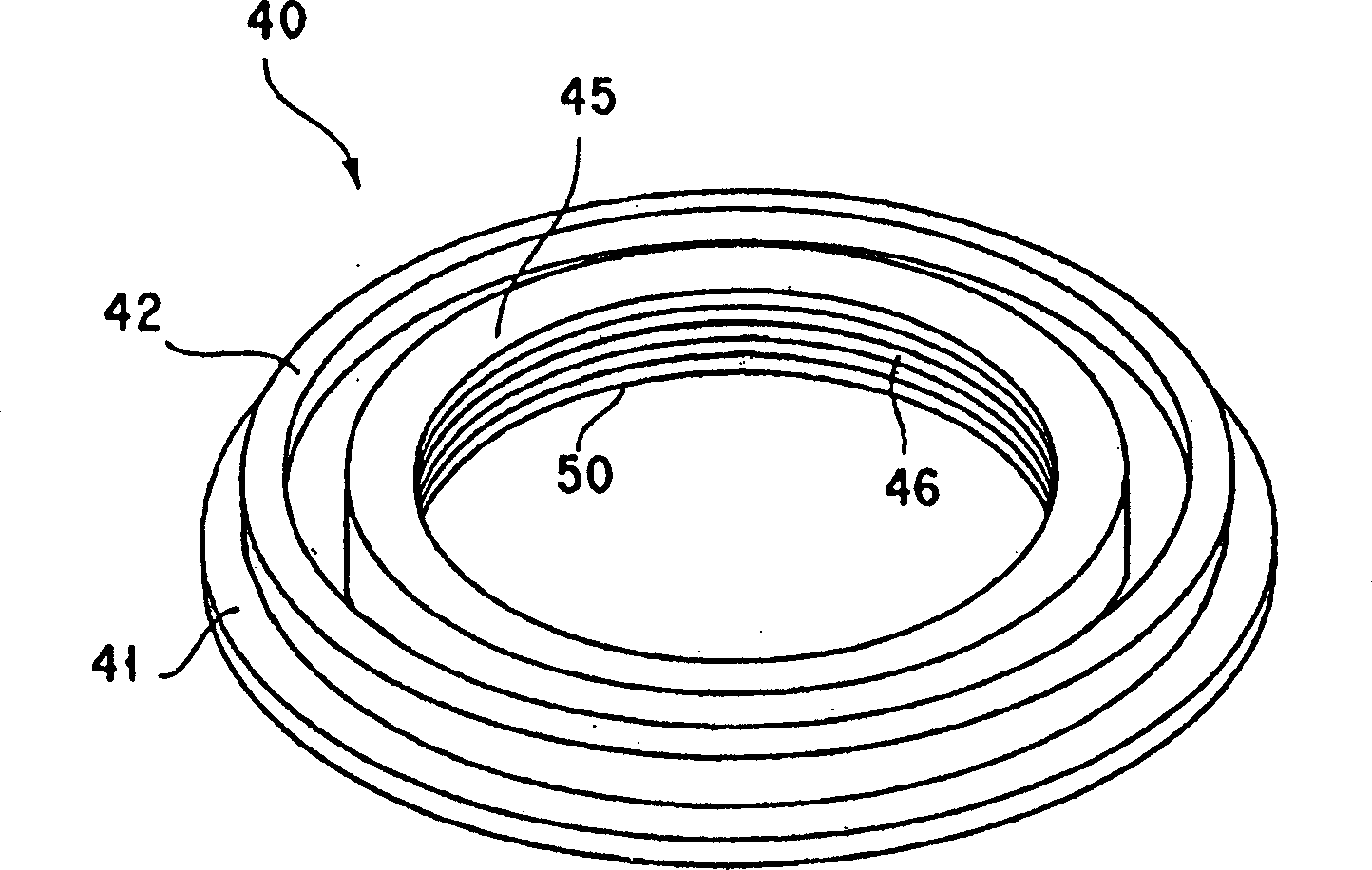
[0194] Figure 9 The male connector part 40a of the illustrated connector 30 has a base portion 41 , an outer ring portion 42 and an inner ring portion 45 .

[0195] A female thread portion 46 is provided on the inner peripheral surface of the inner ring portion 45 . Further, a groove 47 is recessed in the inner peripheral surface of the inner ring portion 45 in the axial direction (cylindrical axis direction) of the inner ring portion 45 . The grooves 47 are provided at predetermined intervals, fo...

Deformed example 2

[0200] Refer to the following Figure 10 Modification 2 of the connector of the present invention will be described.

[0201] The basic structure of Modification 2 is the same as Modification 1, but Modification 2 is characterized by having a handle portion. In addition, in the following description, although the male connector part is used as an example for description, it is also applicable to the female connector part.

[0202] Figure 10 The male connector part 40b of the illustrated connector 30 has a base portion 41, an outer ring portion 42, and an inner ring portion 45 having an internal thread portion 46 and a groove 47 formed by roll forming on the inner peripheral surface thereof.

[0203] exist Figure 10 In the upper end portion of the inner ring portion 45, a handle portion 48 protruding radially is provided. The handle portion 48 is formed in connection with the groove 47, and three are provided at intervals of 120°.

[0204] Here, a method of forming the h...


PUM

PropertyMeasurementUnit
thicknessaaaaaaaaaa
thicknessaaaaaaaaaa
thicknessaaaaaaaaaa

Abstract

PROBLEM TO BE SOLVED: To provide connection structure of a storage element capable of flowing large current, without mentioning the capability of improvement in the workability in connection of two or more elements, as well as the reduction in production cost.SOLUTION: The storage elements are connected each other by mutually abutting on countering end surfaces in the direction of an axis of inner side cylinders 41 and 51 of a male side electrical connection hook 22 and a female side electrical connection hook 32, and also by pressure-welding the circumference surface of an outside cylinder 42 of the male side electrical connection hook 22, and the inner circumference surface of an outside cylinder 52 of the female side electrical connection hook 32. In this way, the male side electrical connection hook 22 and the female side electrical connection hook 32 can be detached and attached with a single touch. A current path is formed between the end sides mutually abutted by the inner side cylinders 41 and 51 of the male side electrical connection hook 22 and the female side electrical connection hook 32, and furthermore a current path is formed between the circumference surface of the outside cylinder 42 of the male side electrical connection hook 22 and the inner circumference surface of the outside cylinder 52 of the female terminal.

Description

technical field [0001] The present invention relates to a connector for electrically connecting terminals and wires, and more particularly, to a quick-fit connector. [0002] The present invention also relates to a cover device for an inter-terminal connection portion for electrical connection by snap fit, and an inter-terminal connection device using the cover device. [0003] The present invention also relates to a storage battery using the above-mentioned quick-fit electrical connector, an electrical storage assembly connected to multiple storage batteries, and an electrical storage device with multiple electrical storage assemblies. [0004] The invention also relates to a storage battery connection structure for connecting storage batteries and a bus bar with the connection structure. Background technique [0005] A socket-type connector is generally used as a connector for electrically connecting terminals of a storage battery or an electric storage element and wiring...

Claims


Application Information

Patent Timeline
Patent Type & Authority Applications(China)
IPC IPC(8): H01R24/06H01R13/629H01M2/30H01G11/10H01G11/12H01G11/66H01G11/74H01G11/78H01G11/82
CPCY02E60/12Y02E60/13Y02E60/10
Inventor 岛守全人冈田知行加藤久山本康一佐佐木秀二长谷川建二大林宗正安田范史川原诚
Owner YKK CORP
Why Eureka
Try Eureka