Arc start control method in robot welding
A technology of robot welding and control methods, which is applied in welding equipment, manufacturing tools, arc welding equipment, etc., can solve the problems of multiple spatters and defects, achieve good arc ignition performance, improve arc ignition performance, and increase arc length.
- Summary
- Abstract
- Description
- Claims
- Application Information
AI Technical Summary
Problems solved by technology
Method used
Image
Examples
Embodiment approach 1
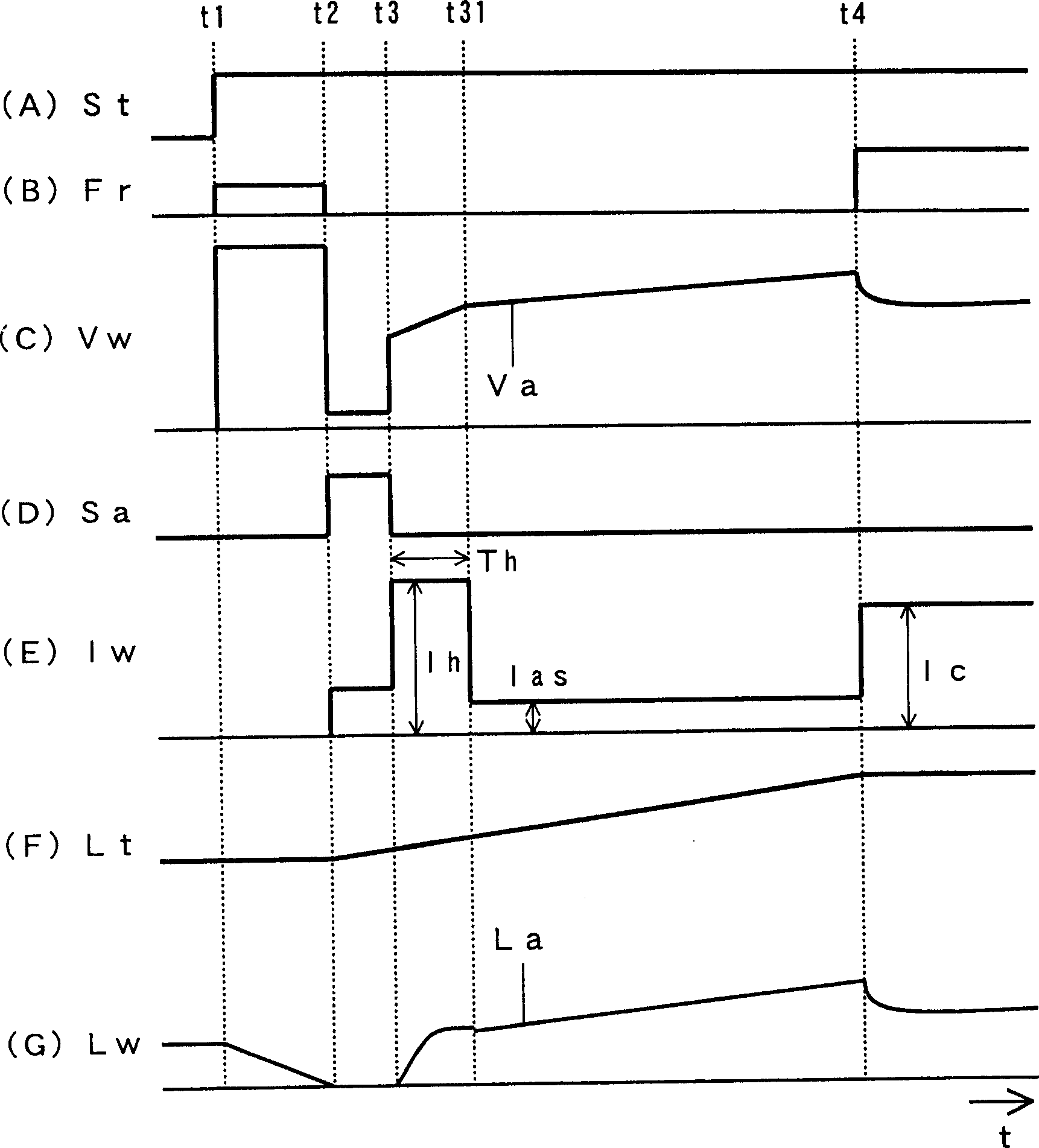
[0033] figure 1 It is a flowchart showing the arc ignition control method of robot welding according to Embodiment 1 of the present invention. Figure (A) shows the time change of the welding start signal St, figure (B) shows the time change of the wire feed speed setting signal Fr, figure (C) shows the time change of the welding voltage Vw, and figure (D) shows the short circuit / arc judgment The time variation of the signal Sa, the diagram (E) represents the time variation of the welding current Iw, the diagram (F) represents the time variation of the distance Lt between the contact tip / base metal, and the diagram (G) represents the distance Lw between the front end of the welding wire / base metal (= Time variation of the arc length La). Regarding the welding device used, the same as the above Figure 5 have the same structure. This figure is similar to the above Figure 6 Correspondingly, the operation before the time t3 is the same, so the description is omitted. Hereina...
Embodiment approach 2
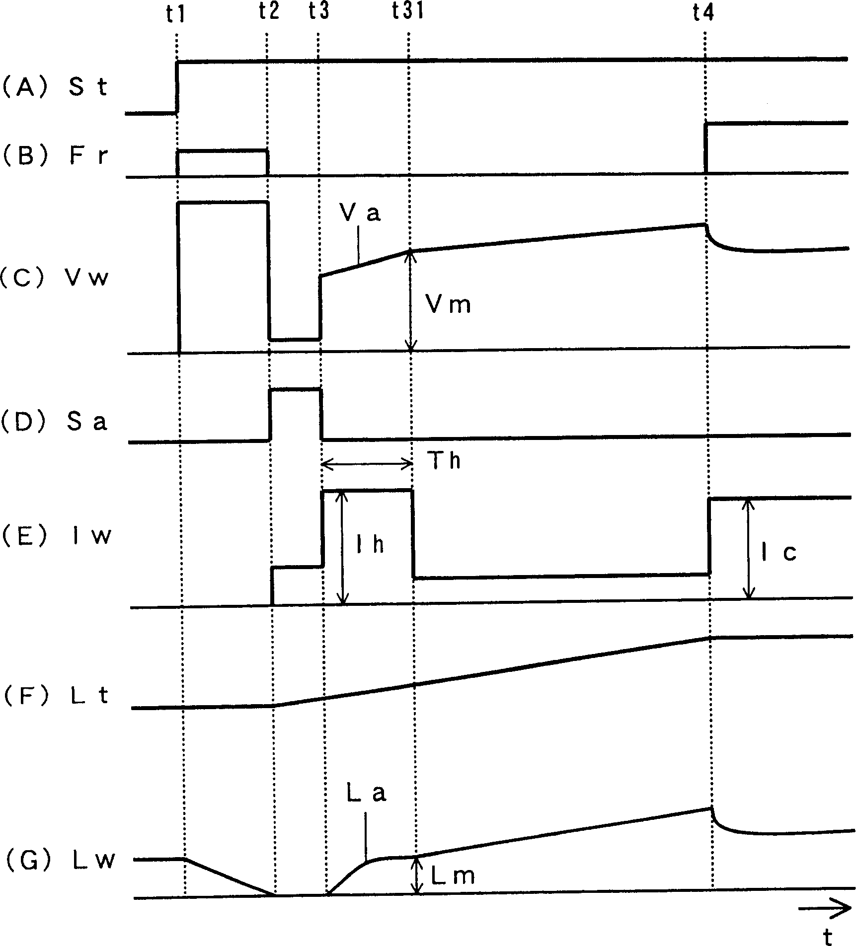
[0037] figure 2 It is a timing chart showing the arc ignition control method of robot welding according to Embodiment 2 of the present invention. This figure is similar to the above figure 1 Correspondingly, only the variable control of Th during re-shorting prevention is different. Hereinafter, this difference will be described with reference to the figure.
[0038] The re-short prevention period Th starts at time t3 when an initial arc is generated, and ends at time t3 when the arc length La reaches a predetermined value Lm. That is, when the arc voltage Va has reached the specified value Vm corresponding to the specified arc length Lm, as shown in figure (C), it is judged that the arc length La has reached the specified value Lm, as shown in figure (G). Thereby, the arc length La at the time when the re-short-circuit prevention period Th ends can always be adjusted to an appropriate value. Therefore, the time required to obtain an appropriate value of Th during the re...
Embodiment approach 3
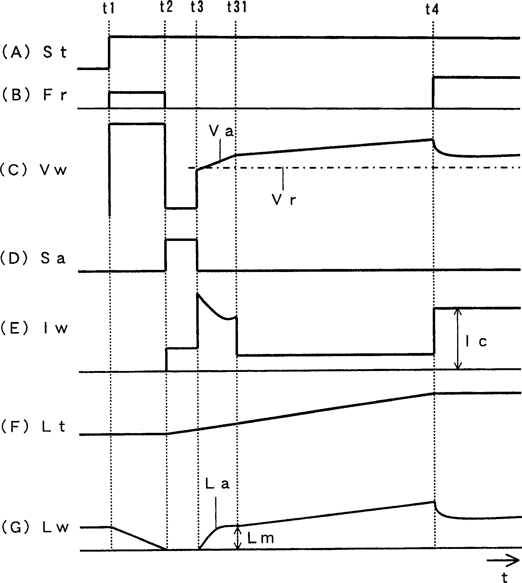
[0040] image 3 It is a timing chart showing the arc ignition control method of robot welding according to Embodiment 3 of the present invention. This figure is similar to the above figure 1 Correspondingly, only the variable control of the re-short circuit prevention current Ih is different. Hereinafter, this difference will be described with reference to this figure.
[0041] The re-short circuit prevention current Ih is controlled so as to be approximately inversely proportional to the change in the arc voltage Va as shown in (C). That is, Ih=f(Va), and the re-short circuit prevention current Ih is changed as a function of the arc voltage Va. There is an inverse proportional relationship in which the re-short circuit prevention current Ih decreases when the arc voltage Va increases. If a function example is given, then Ih=Ih0-70×(Va-Vr). Here, the initial value Ih0≈Ic, and Vr is the set value of the welding voltage. According to this function, when the arc voltage Va...
PUM
 Abstract
Description
Claims
Application Information
 - R&D
- Intellectual Property
- Life Sciences
- Materials
- Tech Scout
- Unparalleled Data Quality
- Higher Quality Content
- 60% Fewer Hallucinations
Browse by: Latest US Patents, China's latest patents, Technical Efficacy Thesaurus, Application Domain, Technology Topic, Popular Technical Reports.
© 2025 PatSnap. All rights reserved.Legal|Privacy policy|Modern Slavery Act Transparency Statement|Sitemap|About US| Contact US: help@patsnap.com


