Preparation of distributed optical fiber sensor reflector

A technology of distributed optical fibers and mirrors, applied in the directions of light guides, optics, instruments, etc., can solve the problems of high cost of fiber grating equipment, grating response function errors, complex additional conditions, etc., and achieve the effect of easy operation and simple mechanism.

Inactive Publication Date: 2007-02-07
天津爱天光电子科技有限公司
View PDF3 Cites 3 Cited by
  • Summary
  • Abstract
  • Description
  • Claims
  • Application Information

AI Technical Summary

Problems solved by technology

In addition to the cost, the above two methods have a common disadvantage: they can only realize the stepwise digital simulation of the required exposure function, and the continuity of the analog function will produce different degrees of error in the response function of the grating.
[0008] As mentioned above

Method used


Image

  • Preparation of distributed optical fiber sensor reflector
  • Preparation of distributed optical fiber sensor reflector
  • Preparation of distributed optical fiber sensor reflector

Examples


Embodiment Construction

[0023] The manufacture of a novel distributed optical fiber sensor reflector of the present invention will be described in detail below in conjunction with the embodiments and accompanying drawings.

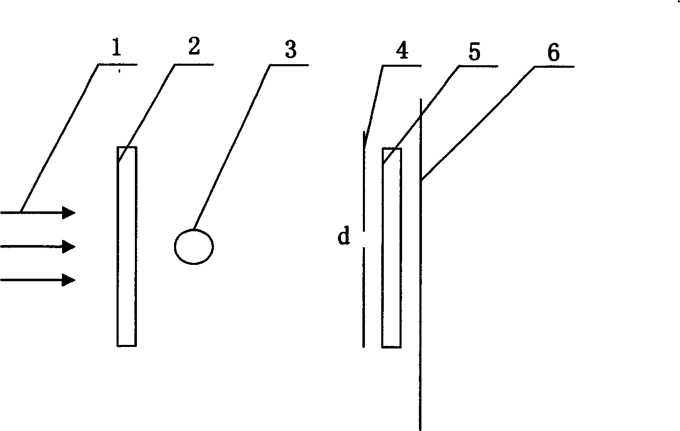
[0024] Such as figure 1 As shown, the manufacture of a novel distributed optical fiber sensor reflector of the present invention includes an ultraviolet laser 1, a cylindrical lens 2, a cylindrical lens 3, a phase template 5, and a slit plate 4. The overall configuration structure is: The ultraviolet laser 1, the cylindrical lens 2, the cylindrical lens 3, the slit plate 4, and the phase template 5 are arranged in sequence.

[0025] Wherein, the ultraviolet laser 1 is selected from one of a 139nm argon ion laser or a 248nm excimer laser.

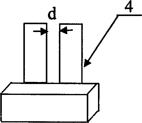
[0026] Such as figure 2 As shown, the slit plate 4 is made of a metal material with good thermal conductivity, its slit width d is adjusted according to the bandwidth width of the fiber grating reflector required, and the slit width d is pro...


PUM


Abstract

The disclosed manufacture method for new distributed optical fiber sensor reflector comprises: a 139nm argon-ion UV laser or 248nm quasi-molecular laser, two column lenses vertical with each other and parallel with a phase template, and a slit made of well-conductive metal to be regulated as requirement on width. This invention can reduce cost without chirp template for industrial production.

Description

technical field [0001] The invention relates to a fiber grating sensor. In particular, it relates to the manufacture of a new type of distributed optical fiber sensor mirror that can be applied in practice, is simple, reliable, stable, and high-precision, and can produce wide bandwidth, low reflectivity, consistency, and uniformity. Background technique [0002] Fiber optic and fiber grating sensors are new types of sensors that have developed rapidly in recent years. Fiber optic and fiber grating sensors can integrate information sensing and transmission. Compared with traditional sensors, it has many advantages: such as explosion-proof, anti-electromagnetic interference, anti- Corrosion, shock resistance, high temperature resistance, small size, light weight, flexible and convenient, especially can be used in harsh environments. [0003] Distributed optical fiber sensing system is the best detection method for leaks in dam projects, strains of large buildings, oil pipelin...

Claims


Application Information

Patent Timeline
IPC IPC(8): G02B6/122G02B5/18
Inventor 董苏姗孟凡勇郭转运马琳萍
Owner 天津爱天光电子科技有限公司
Why Eureka
Try Eureka