Coil sensitivity estimation for parallel imaging

A coil sensitivity and imaging technology, which is applied to the measurement of magnetic variables, measuring devices, instruments, etc., can solve the problems of artifacts, damage, and failure of the sensitivity calibration deployment program, and achieve the effect of improving image quality and reducing position error

Inactive Publication Date: 2007-02-07
KONINKLIJKE PHILIPS ELECTRONICS NV
View PDF0 Cites 10 Cited by
  • Summary
  • Abstract
  • Description
  • Claims
  • Application Information

AI Technical Summary

Problems solved by technology

[0007] In parallel imaging reconstructions, distortion of the sensitivity calibration can lead to failure of the unwrapping procedure, which manifests as overlap-like artifact

Method used


Image

  • Coil sensitivity estimation for parallel imaging
  • Coil sensitivity estimation for parallel imaging
  • Coil sensitivity estimation for parallel imaging

Examples


Embodiment Construction

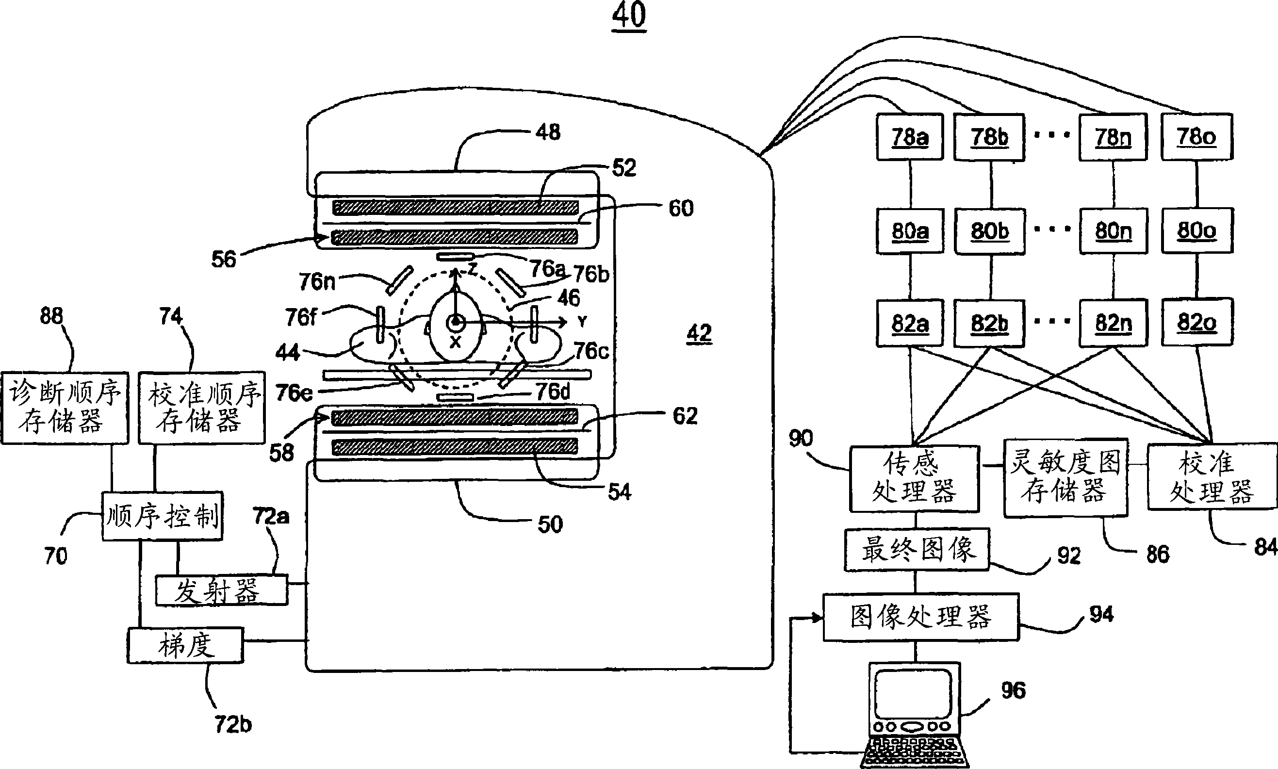
[0024] refer to figure 1 , the magnetic resonance imaging apparatus 40 includes a method for generating a temporally constant B 0 magnetic field of the main magnet 42 system, the B 0 The magnetic field extends vertically in the examination region in the z direction of the xyz coordinate system shown. The region of interest of the patient 44 is placed within an examination volume 46 - typically a spherical area - defined by the FOV of the device. The magnet system includes an iron yoke defining a flux return path between the pole pieces 48 , 50 . Superconducting or resistive coil windings are placed close to the pole pieces 48, 50 or along the flux return path. Alternatively, the yoke may be a permanent magnet.

[0025] Gradient coil systems 52, 54 generate spatially varying magnetic field pulses with approximately linear gradients in the x-, y-, or z-directions. A respective resonator 56, 58 resonating at the Larmor frequency of a selected dipole, eg H1, is arranged betwe...


PUM


Abstract

In a parallel or SENSE imaging technique in an MRI system (40), a calibration scan is conducted to generate a calibration image (86) indicative of sensitivity profiles of parallel imaging coils (76a, . . . ,76n) also in the regions where the magnetic field is distorted. This is accomplished by using a phase refocusing imaging protocol such as a spin echo technique, or by using a gradient echo technique where the echo time is very short. In addition, the phase encode direction of the calibration scan and a diagnostic imaging scan shall be matched. A diagnostic imaging scan is conducted using a diagnostic scan protocol to generate a diagnostic image representation from each parallel imaging coil. A SENSE processor (90) reconstructs a final diagnostic image (92) from the diagnostic image representations and the coil sensitivity profiles.

Description

technical field [0001] The following relates to the field of diagnostic imaging. It has particular application in reducing artifacts in magnetic resonance parallel imaging techniques. Background technique [0002] In a magnetic resonance imaging apparatus for medical diagnosis of the human body, the body axis is usually oriented along the horizontal x-axis of a Cartesian coordinate system. The body region to be examined is located between the pole shoes of the magnet, which generate a time-constant main magnetic field B extending along the vertical or z-axis 0 . A resonator is provided for transmitting excitation signals and receiving resonance signals. When a substance such as body tissue is subjected to a uniform magnetic field B 0 When affected, the individual spin magnetic moments in the tissue are preferentially aligned with this polarization field. If a substance or tissue is subjected to an excited radiofrequency field B in the x-y plane and close to the characte...

Claims


Application Information

Patent Timeline
IPC IPC(8): G01R33/561
CPCG01R33/5611
Inventor A·尼米J·坦图M·伊利豪塔拉
Owner KONINKLIJKE PHILIPS ELECTRONICS NV
Why Eureka
Try Eureka