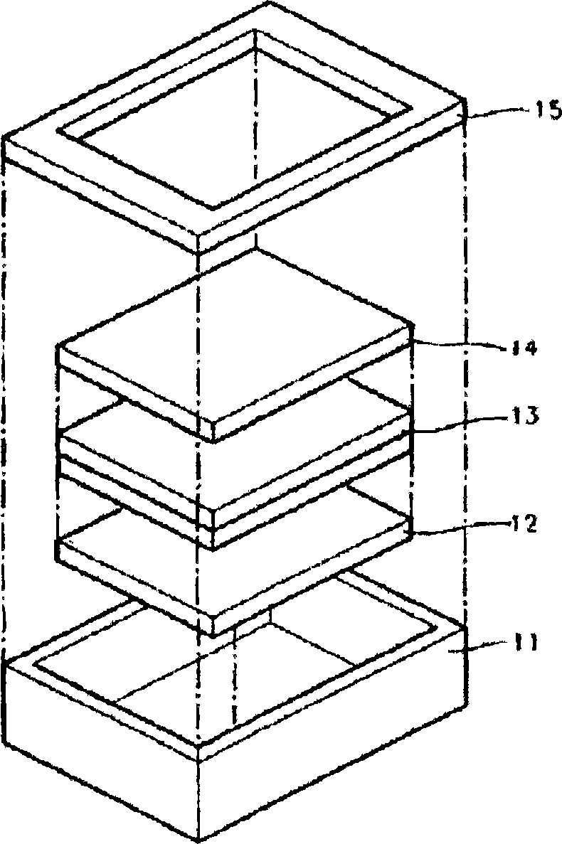
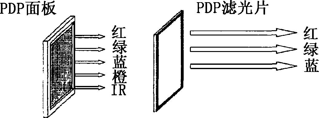
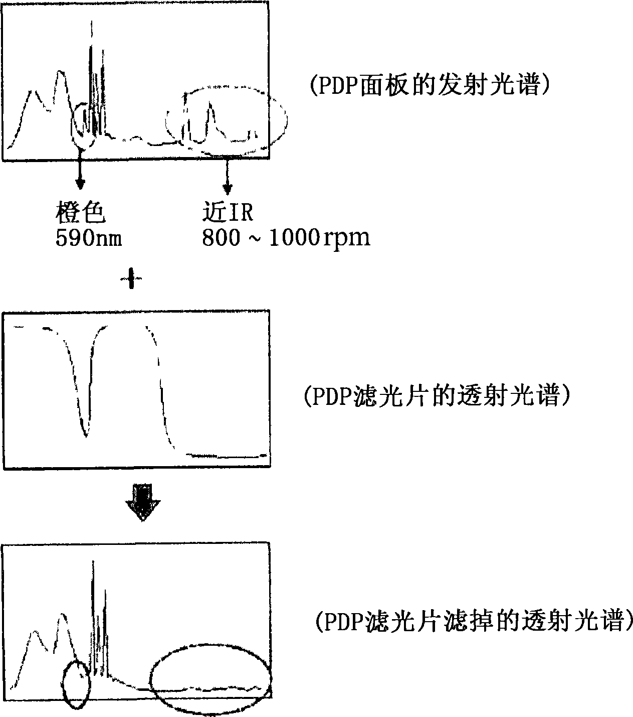
Film for PDP filter, PDP filter comprising the same and plasma display panel produced by using the PDP filter
A plasma and optical filter technology, applied in the field of optical filters, can solve the problems of light transmittance change, diimmonium dye differential thermal stability, etc., achieve good durability and thermal stability, and simplify the method of film formation , the effect of high light transmittance
- Summary
- Abstract
- Description
- Claims
- Application Information
AI Technical Summary
Problems solved by technology
Method used
Image
Examples
Embodiment 1
[0100] Formation of NIR absorbing film
[0101] 27 g of a SAN copolymer (available from LG Chemical) having a weight average molecular weight of 140,000, a Tg of 105° C., and an acrylonitrile content of 27 wt % was dissolved in 73 g of THF to prepare a 27% binder solution. Then, 0.4 g of diimonium salt dye (ADS 1065A) was added to 100 g of the binder solution and stirred to prepare a mixed solution. The mixed solution was coated on a transparent PET film by a bar coating method to a dry coating thickness of 15□. The coating was dried at 120° C. for 5 minutes to prepare a NIR absorbing film. Table 1 shows changes in light transmittance before and after the film was left at 80° C. for 500 hours and at 60° C. and a relative humidity (RH) of 90% for 500 hours. Figure 4 and Figure 5 are the transmission spectra obtained before and after each durability test. The durability of the film for the PDP filter was evaluated by measuring the change in light transmittance of the dye-c...
Embodiment 2
[0103] Formation of NIR absorbing film
[0104] 30 g of a SAN copolymer (available from LG Chemical) having a weight average molecular weight of 140,000, a Tg of 105° C. and an acrylonitrile content of 27 wt % was dissolved in 70 g of MEK to prepare a 30% binder solution. Then, 0.4 g of diimonium salt dye (ADS 1065A) was added to 100 g of the binder solution and stirred to prepare a mixed solution. The mixed solution was coated on a transparent PET film by a bar coating method to a dry coating thickness of 15□. The coating was dried at 120° C. for 5 minutes to prepare a NIR absorbing film. Table 1 shows changes in light transmittance obtained before and after the film was left at 80° C. for 500 hours and at 60° C. and 90% RH for 500 hours. Figure 6 and Figure 7 are the transmission spectra obtained before and after each durability test.
[0105] Visible light range (nm)
Embodiment 3
[0107] Formation of NIR absorbing film
[0108] 27 g of a SAN copolymer (available from LG Chemical) having a weight average molecular weight of 140,000, a Tg of 105° C., and an acrylonitrile content of 27 wt % was dissolved in 73 g of THF to prepare a 27% binder solution. Then, 0.4 g of diimonium salt dye (ADS 1065A) and 0.25 g of dithiol-based nickel complex dye (V-63, purchased from Epoin) were added to 100 g of the binder solution and stirred to prepare get a mixed solution. The mixed solution was coated on a transparent PET film by a bar coating method to a dry coating thickness of 15□. The coating was dried at 120° C. for 5 minutes to prepare a NIR absorbing film. Table 2 shows changes in light transmittance before and after the film was left at 80° C. for 500 hours and at 60° C. and 90% RH for 500 hours. Figure 8 and Figure 9 are the transmission spectra obtained before and after each durability test.
PUM
| Property | Measurement | Unit |
|---|---|---|
| absorption wavelength | aaaaa | aaaaa |
Abstract
Description
Claims
Application Information
 - R&D
- Intellectual Property
- Life Sciences
- Materials
- Tech Scout
- Unparalleled Data Quality
- Higher Quality Content
- 60% Fewer Hallucinations
Browse by: Latest US Patents, China's latest patents, Technical Efficacy Thesaurus, Application Domain, Technology Topic, Popular Technical Reports.
© 2025 PatSnap. All rights reserved.Legal|Privacy policy|Modern Slavery Act Transparency Statement|Sitemap|About US| Contact US: help@patsnap.com


