Battery pack

A battery pack and battery technology, applied in battery pack components, circuits, electrical components, etc., can solve the problems of reducing connection impedance, large connection resistance, and enlarged shell shape, and achieves high production efficiency and reliability. The effect of small connection resistance and shortened connection path

Active Publication Date: 2007-02-14
PANASONIC CORP
View PDF3 Cites 9 Cited by
  • Summary
  • Abstract
  • Description
  • Claims
  • Application Information

AI Technical Summary

Problems solved by technology

[0007] However, in the structure of Patent Document 1, since a space for arranging the protective element and the circuit board is provided between the case and the battery, the outer shape of the case becomes large, and there is a possibility of failure due to movement or vibration of the circuit board or the protective element. It is possible, but it is difficult to fix the circuit board or protective element to the battery or case so that it cannot ensure high reliability, and since it is connected with a lead plate, there is a large connection resistance The problem
[0008] However, in Patent Document 2, although the protective element is fixedly installed on the battery through the terminal bracket, the lead plate is welded on the combination of the battery and the bracket, and is stored in the case to form a battery pack. Therefore, not only the external dimensions become larger, but also The connection resistance is large, and there are many assembly processes, making it difficult to ensure high production efficiency.
[0009] In addition, although Patent Document 3 fixes the circuit board to the sealing plate of the battery by using a special sealing plate having a connection protrusion, the connection resistance can be reduced by the connection structure without using the lead plate, and the structure of the assembly process can be reduced. , but due to the structure of the battery pack that accommodates these circuit boards and batteries in the case, there is a problem that the external dimensions become correspondingly larger
[0010] In addition, Patent Document 4 fixes the protective element and the output terminal to the resin molded part by insert molding the battery, the protective element, and the output terminal, so that the number of parts can be reduced and the structure can be compactly configured, but the insert molding requires equipment cost. And it is difficult to ensure high dimensional accuracy or production efficiency

Method used


Image

  • Battery pack
  • Battery pack
  • Battery pack

Examples


Embodiment 1

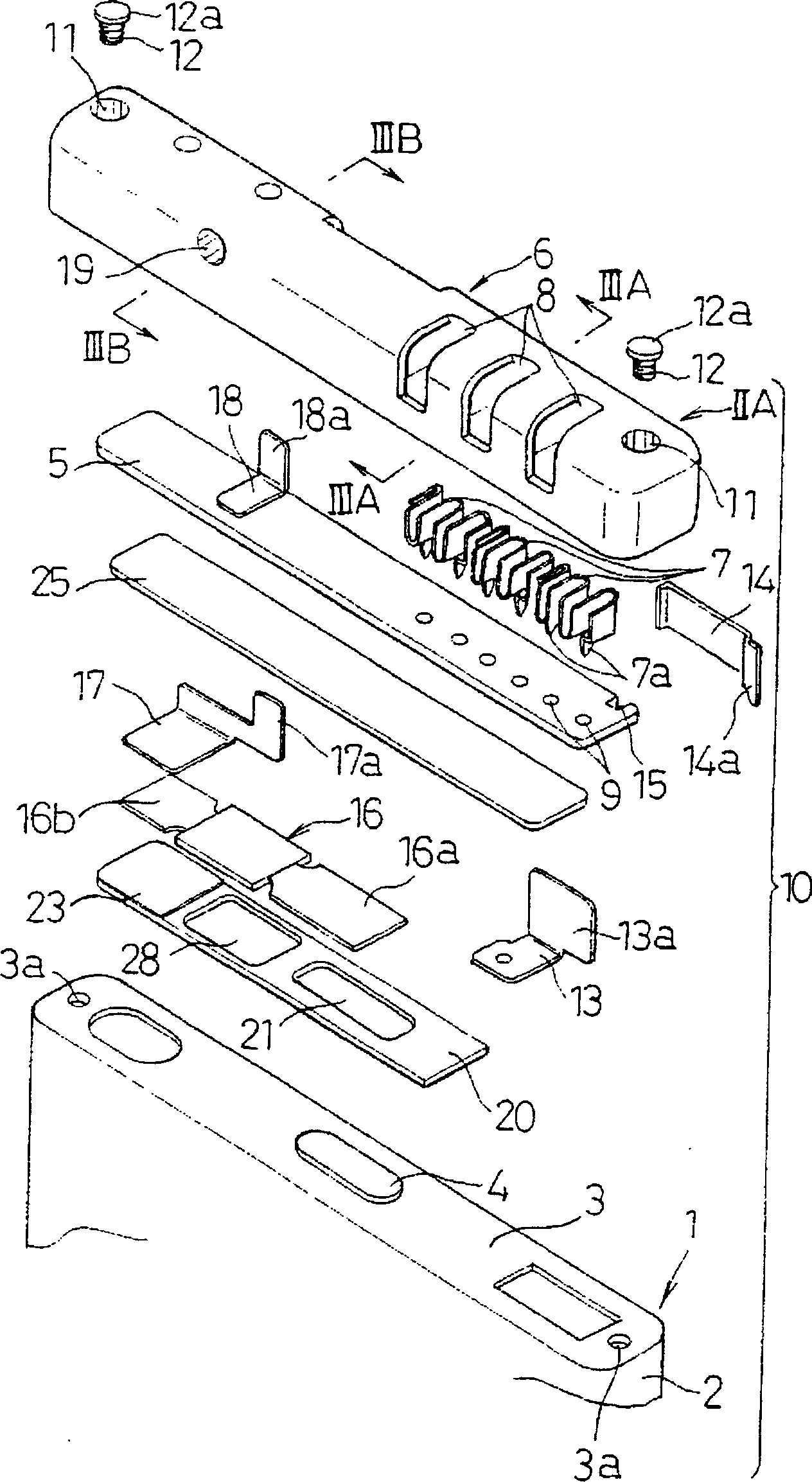
[0048] figure 1 Among them, 1 is a battery whose cross-sectional shape is a flat rectangle or a rectangular or elliptical square corner with an arc-shaped inner corner. The battery 1 is composed of a lithium-ion battery. liquid. The structure of the electrode plate group is a structure in which strip-shaped positive electrode plates and negative electrode plates are wound into a roll with a separator interposed between them, and stacked in multiple layers. The positive plate adopts a structure in which a positive electrode mixture (positive electrode compound) is applied to a core material made of aluminum foil and then dried, and the negative electrode plate adopts a structure in which a negative electrode mixture is coated on a core material made of copper foil and then dried. Composed of microporous polypropylene film, etc.

[0049] An electrode terminal 4 protrudes from the center of the one end surface 3 of the battery case 2 . The electrode terminal 4 penetrates the o...

Embodiment 2

[0070] Next, a second embodiment of the present invention will be described. In addition, the same reference numerals are assigned to the same components as those of the first embodiment described above, their descriptions are omitted, and only the differences will be mainly described.

[0071] The first embodiment describes an example in which the battery case 2 and the end case 6 are fixed together by screwing the top end of the screw 12 into one end face 3 of the battery case 2, while the present embodiment is like Figure 9 ~ Figure 10 As shown, the head 22a of the coupling pin 22 with a head is coupled to the step 11a of the mounting hole 11 at both ends of the end housing 6, and its top end is welded to both ends of the one end surface 3 of the battery case 2. on, thus fixed into one. As the welding method, methods such as spot welding, arc welding, and laser welding can be used, but spot welding which is inexpensive and has good workability is preferable.

[0072] The...

Embodiment 3

[0076] Next, a third embodiment of the battery pack of the present invention will be described. In addition, the same reference numerals are assigned to the same components as those of the above-mentioned second embodiment, and description thereof will be omitted, and only the differences will be mainly described.

[0077] What has been described in the second embodiment is an example in which the top end of the connecting pin 22 is directly resistance-welded to the end face 3 of the battery case 2, but for example, the end face 3 of the battery case 2 is made of aluminum or an aluminum alloy, and the connecting pin 22 In the case of small parts made of iron-based materials such as stainless steel or nickel-plated steel to ensure sufficient strength, it may be difficult to secure the necessary fixing strength and high reliability if they are directly resistance-welded. In order to solve such a problem, the one end surface 3 of the battery case 2 in this embodiment adopts the s...


PUM

PropertyMeasurementUnit
distanceaaaaaaaaaa
depthaaaaaaaaaa

Abstract

The utility model provides a battery pack which is provided with a battery (1), a circuit board (5) and an end part shell (6), wherein the circuit board (5) is provided with a charge and discharge protecting circuit, and is arranged on the end surface (3) of the battery; the end part shell (6) is provided with an external connecting terminal (7); the circuit board (5) is contained and arranged in the inside of the end part shell (6), both ends of the end part shell (6) are respectively combined with a head part (12a), and penetrated screws (12) are fixedly screwed in both ends of the end surface (3) of the battery (1) so as to fix the end part shell (6). The utility model realizes the battery pack which has the advantages of compact structure, small connecting resistance, high reliability and high productive efficiency.

Description

technical field [0001] The present invention relates to a battery pack formed by arranging a circuit board with a charge-discharge protection circuit at one end of a battery, and integrating an end case housing the circuit board with the battery. Background technique [0002] A battery pack that integrates a battery and a circuit board with a charge-discharge protection circuit requires a compact structure, low connection resistance, high reliability of the connection, and high productivity in the manufacturing process. [0003] A conventional battery pack adopts a structure in which a battery, a protective element, or a circuit board are accommodated in a case. As a specific example, it is known that the battery is accommodated in a case with a terminal window, a protective element or a circuit board is arranged in the space provided between the battery and the case, and a lead plate connecting the battery and the circuit board is arranged opposite to the terminal window. ...

Claims


Application Information

Patent Timeline
Patent Type & Authority Applications(China)
IPC IPC(8): H01M2/10
CPCY02E60/10
Inventor 大田晋志白泽胜行山下藤寿雄石丸毅增本兼人今西裕明
Owner PANASONIC CORP
Why Eureka
Try Eureka