Deep N diffusion for trench IGBT

A deep diffusion and trench technology, applied in the field of IGBTs, can solve problems such as reducing on-resistance, and achieve the effects of reducing conversion loss, increasing irradiation dose, and reducing forward voltage drop.

Inactive Publication Date: 2007-02-28
INTERNATIONAL RECTIFIER COEP
View PDF2 Cites 16 Cited by
  • Summary
  • Abstract
  • Description
  • Claims
  • Application Information

AI Technical Summary

Problems solved by technology

[0008] It would be highly desirable to provide a device that has the advantages of the device of patent 6,683,331, but with reduced on-resistance

Method used


Image

  • Deep N diffusion for trench IGBT
  • Deep N diffusion for trench IGBT
  • Deep N diffusion for trench IGBT

Examples


Embodiment Construction

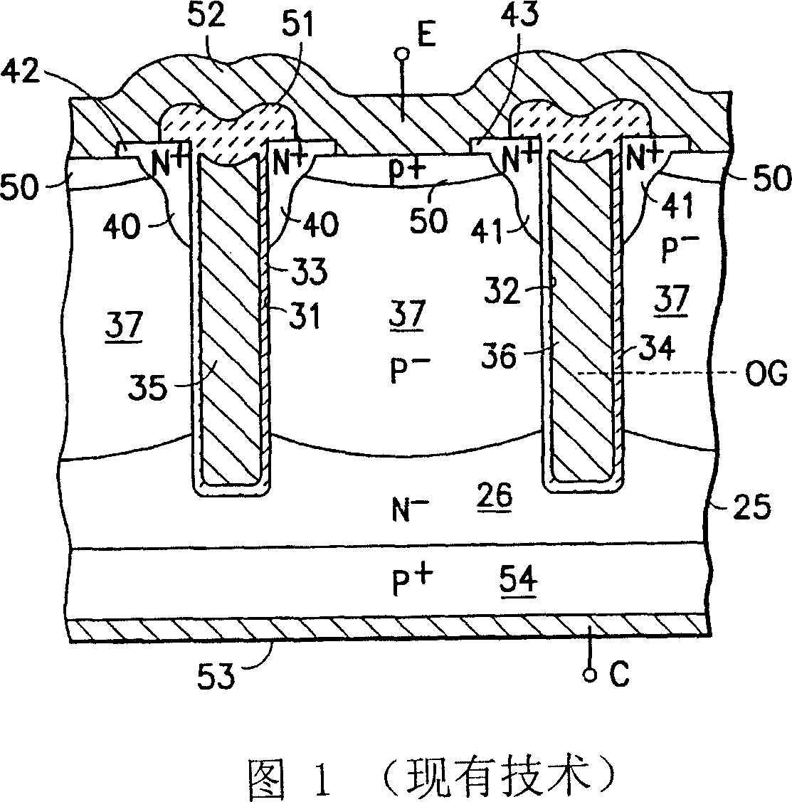
[0020] Referring first to Figure 1, a pair of adjacent units of the prior art structure of patent 6,683,331 are shown in cross-section.

[0021] Fabrication details of the device of FIG. 1 are disclosed in patent 6,683,331, including materials used and process details such as wafer thickness reduction and lifetime limit formation used and collector backside implant 54, among others.

[0022] The structure of Figure 1 is formed in a common starting wafer 25 of floating region material. However, epitaxial wafers may also be used. Wafer 25 has an N-body receiving adjacent deep trenches 31 and 32 lined with thin (eg 1000 A) silicon dioxide gate insulating layers 33 and 34, respectively, and filled with interconnect (not are shown and have external gate terminals G, schematically shown) conductive polysilicon gates 35 and 36 . Trenches 31 and 32 may be about 1.5 microns wide, spaced about 5-10 microns apart and may have a depth of 4-9 microns, and preferably about 6.5 microns. T...


PUM


Abstract

The present invention relates to a deep N diffusion for trench IGBT. An increased conductivity deep diffusion of the same conductivity type as that of the drift region is provided between adjacent trenches of a trench type IGBT and below the trenches to reduce the on resistance components of the drift region resistance and spreading resistance to current flow when the device is turned on. The deep diffusion has a higher concentration than that of the drift region, and has a width of from 4 to 10 microns. The wafer or die has a total width (or thickness) of about 70 to about 300 microns.

Description

technical field [0001] The present invention relates to trench-type insulated gate bipolar transistors (Insulated Gate Bipolar Transistor, IGBTs), and more particularly to IGBTs with reduced forward voltage drop. Background technique [0002] IGBTs are well known and frequently implemented with a planar grid or stripe type layout. These devices have an inherent JFET which increases the device on-resistance R DSON , thereby increasing the forward voltage drop V CE(ON) . Also, such devices have an inherent four-layer parasitic thyristor structure that will latch off if the thyristor's NPN transistor is on. [0003] It is known that IGBTs can be fabricated with trench layouts that eliminate the inherent JFETs of planar devices. However, trench IGBTs still have an inherent four-layer structure, whereby if the inherent NPN transistor in a four-layer device turns on (if current flows through R B′ high enough), the device will latch off. It is also desirable not to increase R...

Claims


Application Information

Patent Timeline
Patent Type & Authority Applications(China)
IPC IPC(8): H01L29/739H01L29/36
CPCH01L29/7397H01L29/66348H01L29/70H01L29/73
Inventor R·弗朗西斯C·额
Owner INTERNATIONAL RECTIFIER COEP
Why Eureka
Try Eureka