Waste gas purifier

A technology of exhaust gas purifier and exhaust gas purification device, which is applied in chemical instruments and methods, exhaust devices, machines/engines, etc., can solve the problems of short service life of exhaust gas purification device and reduced ability of separation and purification treatment.

Inactive Publication Date: 2007-03-07
陈妙生 +1
View PDF0 Cites 10 Cited by
  • Summary
  • Abstract
  • Description
  • Claims
  • Application Information

AI Technical Summary

Problems solved by technology

Due to the structure of the above two types of traps, after use, it will cause the fine dust particles contained in the traps and the trapped exhaust gas to block the gas filtration channel, which affects the impact of the two types of traps. The actual effect of trapping the fine dust particles con

Method used


Image

  • Waste gas purifier
  • Waste gas purifier

Examples


Embodiment Construction

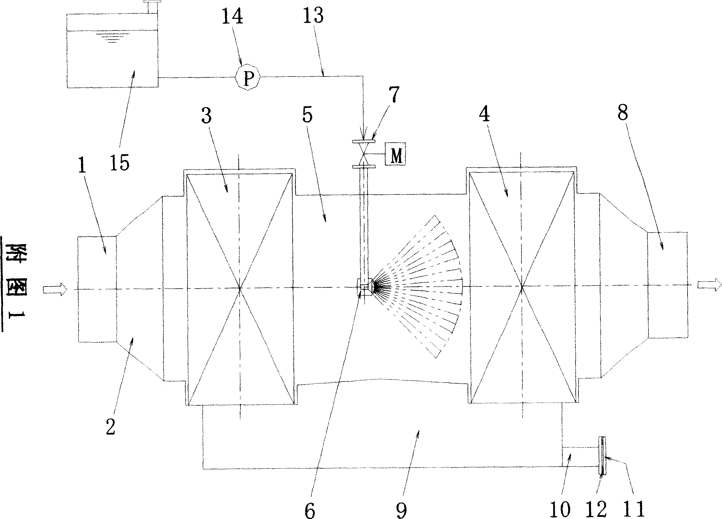
[0015] The device of the present invention will be further described below in conjunction with the embodiments and accompanying drawings.

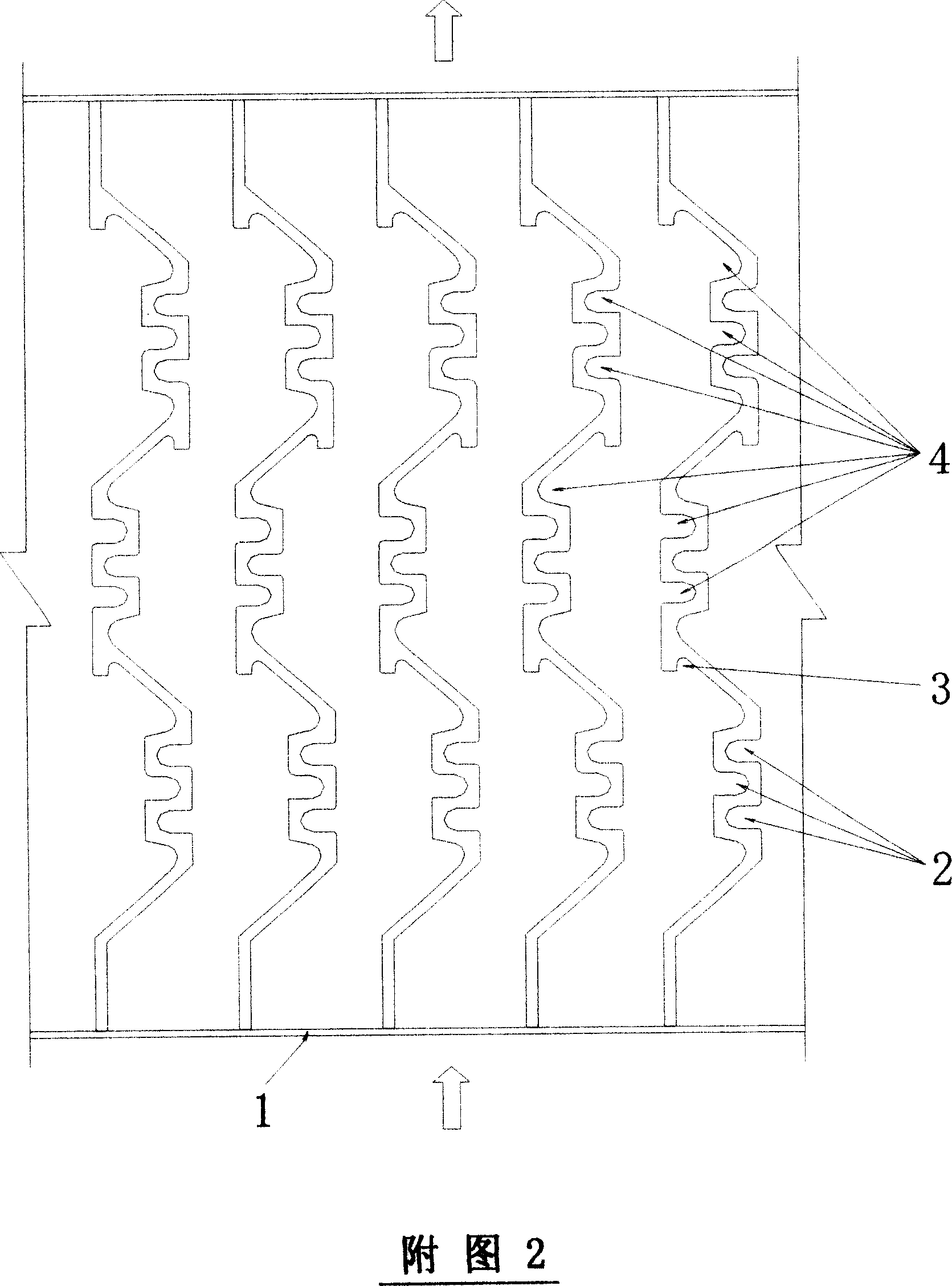
[0016] As shown in Figure 1, when the exhaust gas produced by the incomplete combustion of the fuel internal combustion engine enters the exhaust gas inlet pipe 2 in the exhaust gas purifier housing 1, the exhaust gas after the separation and purification treatment by the first-stage exhaust gas purification device 3 There will be some turbulent flow, and the exhaust gas will flow into the second-stage exhaust gas purification device 6 after being rectified by the exhaust gas rectification channel 4 arranged at a distance between the first-stage exhaust gas purification device 3 and the second-stage exhaust gas purification device 6 at a distance of 800 mm to 1000 mm. Re-separation and purification are carried out. The spray sprinkler 5 in the exhaust gas rectification channel 4 is arranged in front of the second-stage exhaust gas purifica...


PUM


Abstract

The invention relates to a waste gas purifier which can purify the dust in the waste gad of fuel internal-combustion engine. Wherein, the invention is characterized in that: the waste gas via the first waste gas filter is separated into turbulence flow, to be rectified by waste gas rectify channel and sprayed with sprayer with aquacare, to enter into second waste gas filter to be processed; then it will contact the ternary catalyst coated on the porous ceramic carrier grid surface, to oxidize the carbon hydrogen compound and carbon oxide into carbon dioxide and water, and reduce the nitrogen oxide into nitrogen gas, while its purification rate is 95%; the water can absorb dust at 99% efficiency; the liquid drop will deposited into waste liquid storage groove, to be discharge via outlet tube.

Description

technical field [0001] The patent of the present invention relates to an exhaust gas purifier, in particular to an exhaust gas purifier in a fuel internal combustion engine exhaust emission treatment system. Background technique [0002] Due to the exhaust gas purification device in the exhaust gas emission treatment system of the fuel internal combustion engine, in the foreign application technology and process, the second-level exhaust gas purification treatment method is adopted; the oxidation catalytic converter coated with the three-way catalyst is installed on the first-level structure. Hydrocarbons (HC) and carbon monoxide (CO) in exhaust emissions are oxidized to carbon dioxide (CO 2 ) and moisture (H 2 O), reducing nitrogen oxides (NOx) to nitrogen (NO) and oxygen (O 2 ) and other purification treatment methods; a cylindrical gas filter channel collector made of sintered metal plates or a microporous honeycomb linear T-shaped gas filter channel type ceramic is ins...

Claims


Application Information

Patent Timeline
IPC IPC(8): B01D53/94F01N3/10
CPCY02T10/12
Inventor 陈妙生刘建嵩
Owner 陈妙生
Why Eureka
Try Eureka