Internal-combustion engine

A technology for internal combustion engines and combustion chambers, applied in the field of piston reciprocating internal combustion engines, can solve the problems of low combustion efficiency, slow piston down speed, low fuel economy, etc., and achieve the goals of reducing costs, improving adaptability, and improving the power-to-mass ratio of the whole machine Effect

Inactive Publication Date: 2007-03-14
袁辉
View PDF0 Cites 13 Cited by
  • Summary
  • Abstract
  • Description
  • Claims
  • Application Information

AI Technical Summary

Problems solved by technology

[0005] 3. Although lowering the compression ratio can reduce NOx emissions and fuel anti-knock requirements to a certain extent, a low compression ratio means low combustion efficiency, that is, low fuel economy;
[0006] 4. In order to pursue higher combustion efficiency, the combustion process is controlled as far as possible near the top dead center of the piston. At this time, the downward speed of the piston is slower and the pressure rise rate is higher, resulting in greater mechanical impact and combustion noise

Method used


Image

  • Internal-combustion engine
  • Internal-combustion engine
  • Internal-combustion engine

Examples


Embodiment 1

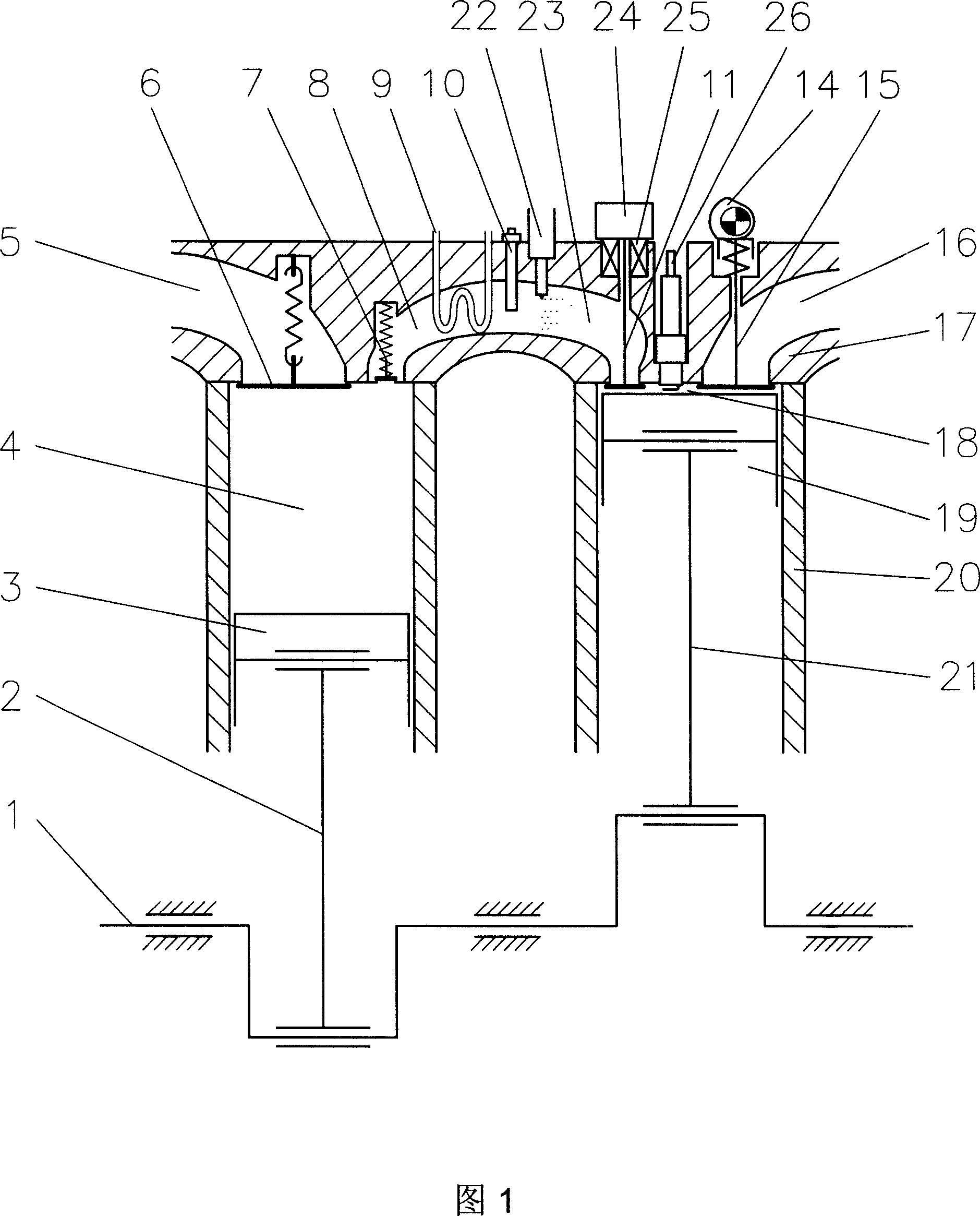
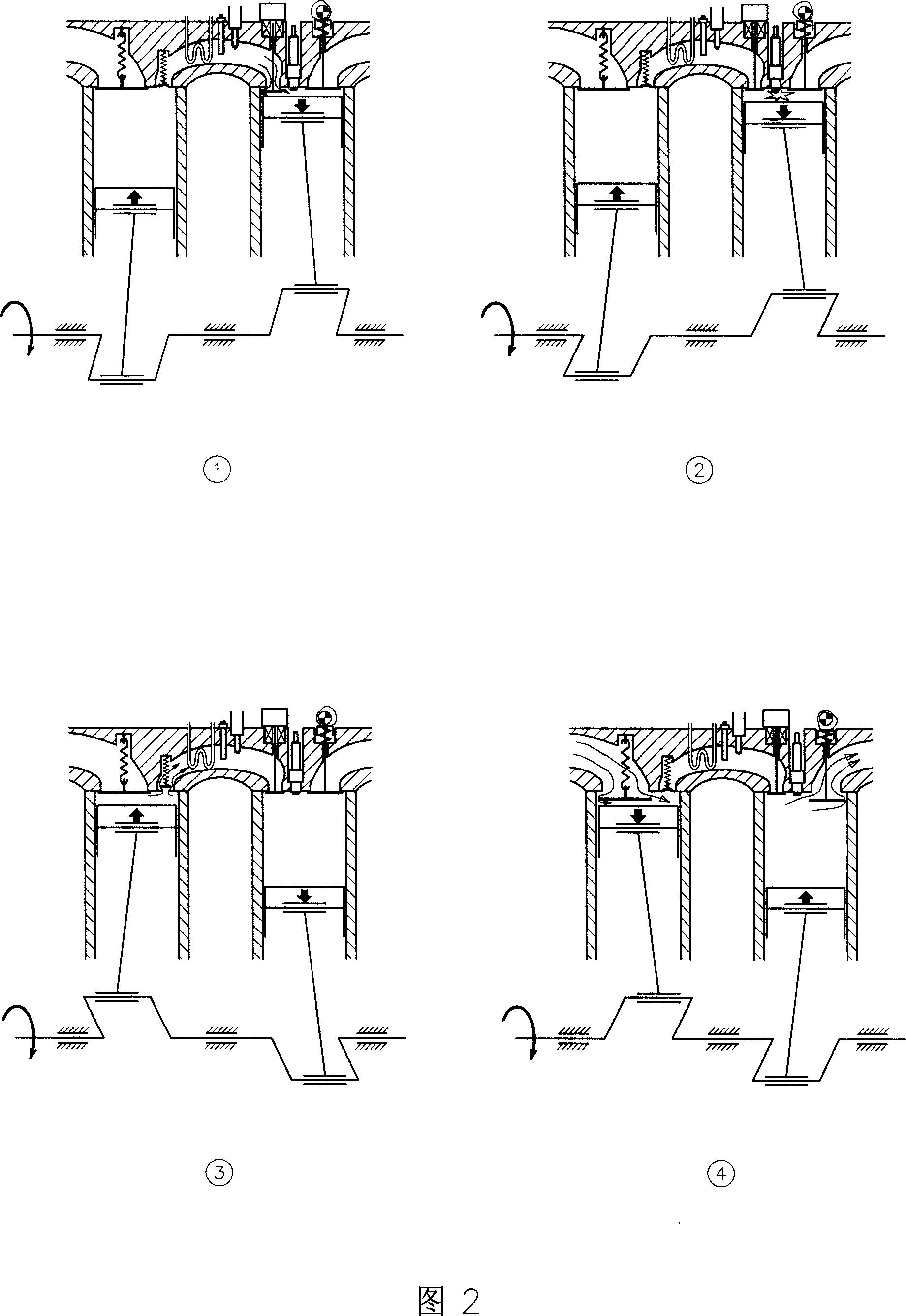
[0035] Embodiment 1, in conjunction with Fig. 1 and Fig. 2, in the first embodiment shown, the internal combustion engine works in the ignition mode and uses gasoline as fuel. The combustion chamber 18 unit includes a cylinder block 20, a cylinder head 17, a piston 19, a crankshaft 1 and a connecting rod 21. The piston 19 reciprocates in the cylinder block 20 and is connected to the crankshaft 1 through the connecting rod 21. The top space of the piston 19 is formed by the cylinder head 17. The combustion chamber 18 is sealed and formed. In the cylinder head 17, an intake valve 11, an exhaust valve 15 and a spark plug 26 are arranged on the top of the combustion chamber 18. The intake valve 11 is driven by the intake valve driving device 24, and the exhaust valve 15 is driven by The exhaust valve cam 14 is driven, the intake valve driving device 24 is provided with an intake valve position sensor 25, and an air compression unit 4 is also provided in the cylinder block 20 outsi...

Embodiment 2

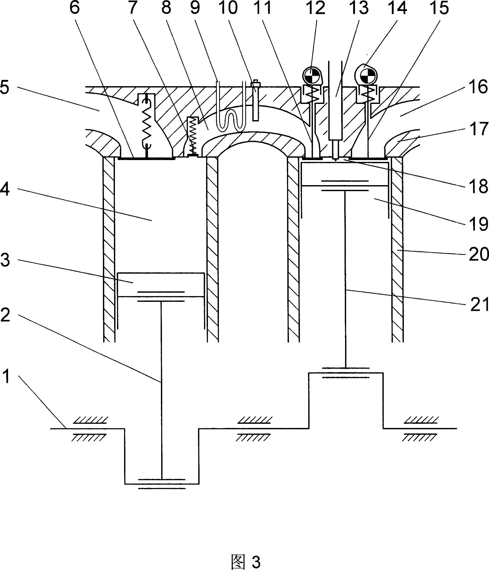
[0037] Embodiment 2, referring to Fig. 3 and Fig. 4, in the second embodiment shown, the internal combustion engine works in compression ignition mode and uses diesel as fuel. The combustion chamber 18 unit includes a cylinder block 20, a cylinder head 17, a piston 19, a crankshaft 1 and a connecting rod 21. The piston 19 reciprocates in the cylinder block 20 and is connected to the crankshaft 1 through the connecting rod 21. The top space of the piston 19 is formed by the cylinder head 17. The combustion chamber 18 is sealed and formed. In the cylinder head 17, the upper part of the combustion chamber 18 is provided with an intake valve 11, an exhaust valve 15 and a fuel injector 13. The intake valve 11 is driven by the intake valve cam 12, and the exhaust valve 15 is driven by the intake valve cam 12. The exhaust valve cam 14 is driven, and an air compression unit 4 is also provided in the cylinder block 20 outside the combustion chamber 18. The air compression unit 4 include...


PUM


Abstract

The invention relates to an internal-combustion engine with piston reciprocating, comprising body, cover, piston, crankshaft and connecting bar. The piston moves advance and return and is connected with crankshaft through connecting bar. The space on the top of piston sealed by cover is formed blast chamber. Intake valve, air outlet valve and spark plug are set in cover at the top of blast chamber. In said body except blast chamber air compressed unit is set, which comprises inhalation valve, air outlet valve, assistant piston, which can move advance and return, and be connected with said crank shaft through assistant connecting bare, and assistant connecting bar. The outlet of air outlet valve is connected to hollow air conversation room withstanding pressure, in which thermal converter, temperature sensor, fuel nozzle and fuel evaporating and mixing room. The outlet of air conversation room is connected to said inlet of intake valve in blast chamber. The invention can decrease harmful gas NOx released largely because of low temperature, improve work efficiency of gas and decrease burning noise.

Description

technical field [0001] The invention relates to a piston reciprocating internal combustion engine. Background technique [0002] At present, the working principle of the known piston reciprocating internal combustion engine has four strokes consisting of "intake" stroke, "compression" stroke, "combustion expansion" stroke and "exhaust" stroke and "compression (and ventilation)" stroke and The two modes of two strokes composed of "combustion expansion (and ventilation)" strokes have the common feature that the compression and combustion expansion processes are completed in the combustion chamber, that is, the gas working medium (fresh air or fuel-air mixture) After being compressed to high temperature and high pressure in the combustion chamber, it immediately enters the combustion expansion process in the combustion chamber, which brings the following principle defects in practical application: [0003] 1. Due to the extremely high combustion temperature, a large amount of ...

Claims


Application Information

Patent Timeline
Patent Type & Authority Applications(China)
IPC IPC(8): F02B23/10F02B33/44F02D13/00
CPCY02T10/125Y02T10/12
Inventor 袁辉袁晓斌王军如袁卫兵刘敏
Owner 袁辉
Why Eureka
Try Eureka