Hydraulic control system for viscosity speed regulation clutch

A hydraulic control system and clutch technology, applied in clutches, fluid clutches, mechanical equipment, etc., can solve problems such as unfavorable operation and maintenance, large resistance loss of coolers, and oil-water mixing of fluid-viscous speed-regulating clutches. The effect of operation operation and maintenance operation, improving operation reliability and improving work reliability

Inactive Publication Date: 2007-03-14
夏学苏
View PDF0 Cites 14 Cited by
  • Summary
  • Abstract
  • Description
  • Claims
  • Application Information

AI Technical Summary

Problems solved by technology

[0003] ①High-temperature hydraulic oil carries too many pollutants (mainly wear debris) during operation, which often causes blockage of the essential oil filter and electro-hydraulic proportional overflow valve, affecting the normal operation of the hydraulic-viscous speed-regulating clutch
[0004] ②The traditional oil cooler used has low compressive strength and is connected to the outlet of the lubricating oil pump. When the oil pressure or cooling water pressure rises, it is easy to break through the metal heat exchange surface of the cooler, resulting in liquid viscosity adjustment. Accident of mixing oil and water in high-speed clutch
[0005] ③Because the

Method used


Image

  • Hydraulic control system for viscosity speed regulation clutch
  • Hydraulic control system for viscosity speed regulation clutch

Examples


Embodiment Construction

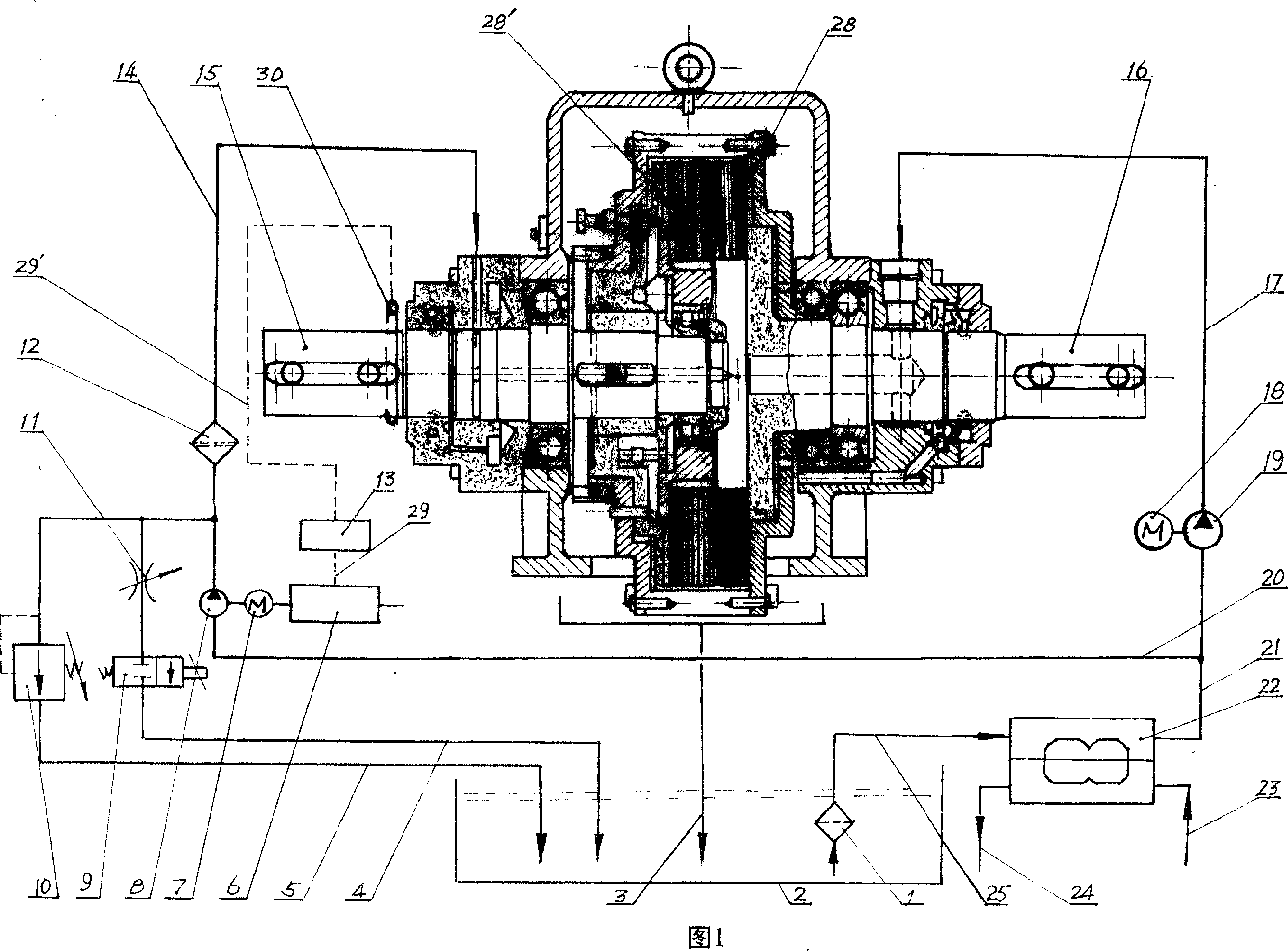
[0017] The specific implementation manners of the present invention will be further described in detail below in conjunction with the accompanying drawings.

[0018] For the sake of clarity, the main engine of the clutch related to the new hydraulic control system of the fluid-viscous speed-adjusting clutch is also marked in Fig. 1 . The driving shaft 16 of the clutch main frame is connected with the shaft of the corresponding motor, and the rotating speed of the driving shaft 16 is equal to the rotating speed of the connected motor, which is constant, while the driven shaft 15 of the clutch main machine is connected to the working machine (such as fan, water pump, or other large industrial equipment, etc.), the rotating speed of the driven shaft 15 is determined according to the required rotating speed of the working machine in a certain period of time, so the rotating speed of the driven shaft 15 changes. The driving shaft 16 is connected with the active friction plate 28, a...


PUM


Abstract

The invention discloses to a new hydraulic-control system applied in air fan, pump or hydro vicious speed governing clutch of soft-starting in other larger scale equipment. Hydraulic oil in oil tank 2 is used to lubricate, cool and transmit torque to positive frictional plate 28 and negative friction plate 28'through outlet pipe 21 of heat exchange of heat pipe 22, pump with lubricated oil 19, inlet of positive shaft 16 of clutch host by oil pipe 17; another oil is used to connect positive frictional plate 28 and negative friction plate 28'through oil delivery pipe 20, controlling oil pump 8, finish filter 12 and the inlet of negative shaft 15 by oil pipe 14. When adjusting speed, only setting speed value of controller 13 is changed. Controller 13 controls converter 6 and motor 7 to adjust speed and then oil pressure on inlet of negative 15 is changed.

Description

technical field [0001] The invention relates to a hydraulic control system, in particular to a hydraulic control system which can be used for a fluid-viscous speed-regulating clutch connected with a high-speed rotary working machine in equipment such as fans and water pumps. Background technique [0002] The hydraulic viscous speed regulating clutch is composed of a speed regulating host and a hydraulic control system. Its structure is usually: a part of the high-temperature hydraulic oil in the oil tank is sucked by the lubricating oil pump and discharged into the cooler after oil filtration, and the cooled oil is then sent to the cooler. The drive shaft end of the speed-regulating main engine is lubricated for the friction plate to cool the friction plate, and the other part of the high-temperature hydraulic oil is absorbed by the control oil pump after the oil filter and discharged into the essential oil filter, and then returned to the oil tank through the electro-hydraul...

Claims


Application Information

Patent Timeline
IPC IPC(8): F16D35/00
Inventor 夏学苏刘丰农
Owner 夏学苏
Why Eureka
Try Eureka