Active optics current transformer and its method

A technology of current transformer and active optics, which is applied in the direction of inductors, instruments, circuits, etc., can solve the problems that the transformer cannot meet the requirements of long-term stable operation, the transformer cannot run continuously and stably for a long time, and the measurement accuracy of the transformer is not high. , to achieve the effect of reducing the cost of optical transmission, simple structure and strong anti-interference ability

Inactive Publication Date: 2007-03-14
北京许继电力光学技术有限公司
View PDF1 Cites 12 Cited by
  • Summary
  • Abstract
  • Description
  • Claims
  • Application Information

AI Technical Summary

Problems solved by technology

The characteristics of semiconductor materials determine that the life of high-power lasers is generally only about a few years, which is far from meeting the requirements of power system measurement for long-term stable operation of transformers
[0007] Due to the above reasons, th...

Method used


Image

  • Active optics current transformer and its method
  • Active optics current transformer and its method
  • Active optics current transformer and its method

Examples


Embodiment Construction

[0027] The present invention is described in further detail in conjunction with accompanying drawing and embodiment:

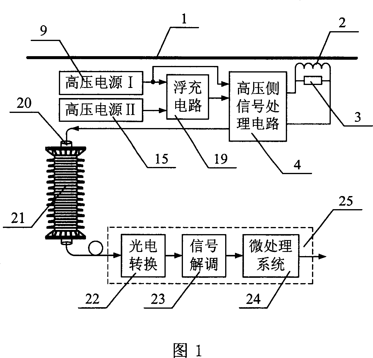
[0028] As shown in FIG. 1 , this embodiment includes a high voltage side signal processing circuit 4 , a high voltage DC power supply 9 , a high voltage DC power supply 15 , a floating charge circuit 19 , a coupling capacitor 21 and a low voltage side signal processing circuit 25 .

[0029] A small high-precision electromagnetic current transformer 2 is installed on the measured current bus 1. The current transformer 2 converts the large current signal on the measured bus 1 into a small current signal. Since the primary and secondary windings are at the same high potential, there is no need to Considering the high-voltage insulation problem, the volume of the current transformer 2 can be made very small; the secondary circuit of the current transformer 2 is provided with a precision sampling resistor 3, and the sampling resistor 3 converts the current signal in...


PUM


Abstract

This invention discloses one source chemical current inductor, which comprises high voltage side signal process circuit 4, high voltage current source 9, high voltage current power 15 and coupler capacitor with non-metal cable 20 and low side signal process circuit 25, wherein, the circuit 4 adopts main and assistant power; the capacitor supply forms main power 9 and laser supply forms assistant power 15 at cooling status under control of side micro process system 24 output level.

Description

technical field [0001] The invention relates to the technical field of current transformers, in particular to an active optical current transformer and a method thereof for measuring high voltage and large current in a power system. Background technique [0002] With the continuous increase of power transmission capacity and the continuous improvement of voltage level, the defects of traditional electromagnetic current transformers such as difficult insulation, complex structure, bulky size, and difficulty in meeting the requirements of power system digitization have become more and more obvious. With the development of modern optical fiber technology and electronic technology, optical current transformers have attracted more and more attention from researchers all over the world, making them an ideal substitute for traditional electromagnetic current transformers. According to whether the current sensing head on the high-voltage side needs a working power supply, the curren...

Claims


Application Information

Patent Timeline
IPC IPC(8): H01F38/32G01R15/00
Inventor 郭志忠于文斌李岩松王贵忠张国庆
Owner 北京许继电力光学技术有限公司
Why Eureka
Try Eureka