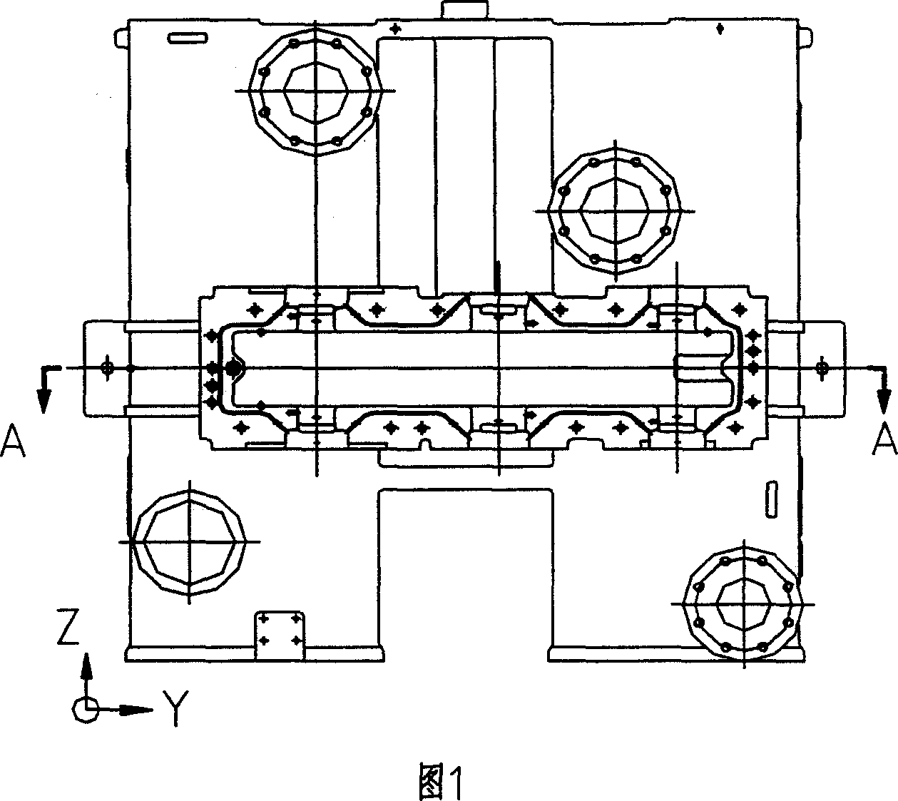
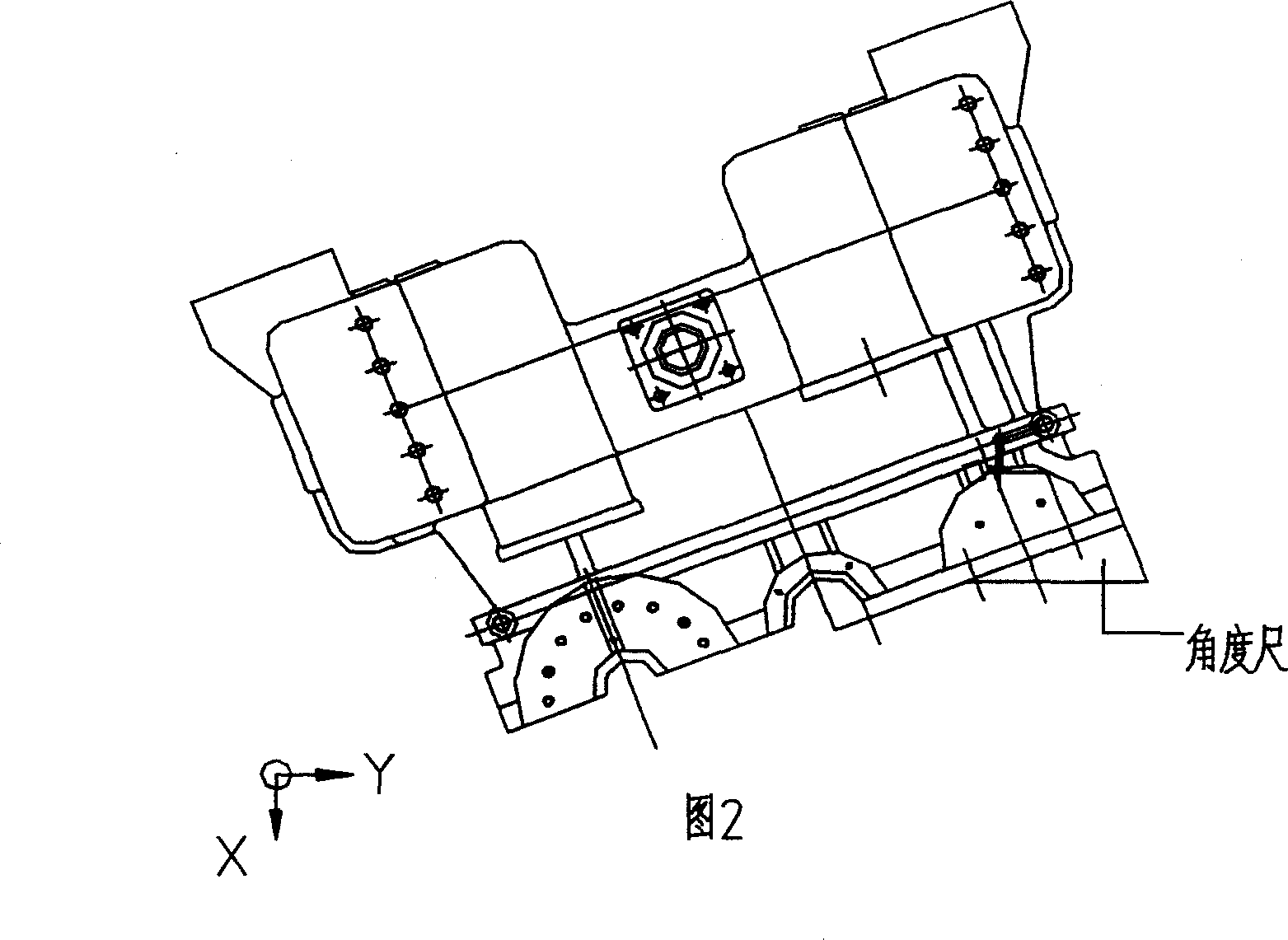
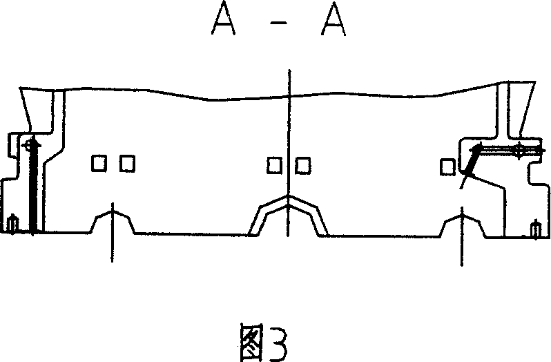
Making process of gear box casing for centrifugal compressor
A technology for centrifugal compressors and gear boxes, which is applied in the manufacture of tools, components with teeth, transmission boxes, etc. It can solve problems such as clamping, high number of circulations, poor machining accuracy of split surfaces, and extended auxiliary time. Achieve high production efficiency, reduce processing costs, and improve roughness
- Summary
- Abstract
- Description
- Claims
- Application Information
AI Technical Summary
Problems solved by technology
Method used
Image
Examples
Embodiment 1
[0045] The gearbox casing of the centrifugal compressor of the present invention is mainly formed by connecting the upper and lower gearbox casings with bolts. The outer dimensions of the upper and lower gearbox shells are 1687mm×1862mm×1518mm, and the processing equipment adopts the gantry-type five-face CNC machine tool for processing.
[0046] 1. The manufacturing process of the lower gear case is as follows:
[0047] (1) Blank forming: The material of the lower gear box is cast with QT400-18 ductile iron; perform the following mechanical processing according to the drawing requirements;
[0048] (2) Marking: marking the bottom surface, bearing hole processing line;
[0049] (3), planing: leave a margin of 2mm on the bottom surface of the planing;
[0050] (4) Using gantry-type five-face CNC machine tools for cutting: semi-finishing and finishing milling of the bottom surface, drilling;
[0051] The rough milling cutter with a diameter of 200mm is used for semi-finish mi...
Embodiment 2
[0081] The gearbox casing of the centrifugal compressor of the present invention is mainly formed by connecting the upper and lower gearbox casings with bolts. The outer dimensions of the upper and lower gearbox shells are: 1687mm×1862mm×1518mm, and the processing equipment adopts the gantry type five-sided CNC machine tool for processing.
[0082] 1. The manufacturing process of the lower gear case is as follows:
[0083] (1) Blank forming: The material of the lower gear box is cast with ductile iron with the brand name QT-40018; the following machining is carried out according to the requirements of the drawings;
[0084] (2) Marking: marking the bottom surface, bearing hole processing line;
[0085] (3), planing: the remaining allowance on the bottom surface of planing is: 2mm;
[0086] (4) Using gantry-type five-face CNC machine tools for cutting: semi-finishing and finishing milling of the bottom surface, drilling;
[0087] The rough milling cutter with a diameter of 2...
Embodiment 3
[0113] The gearbox casing of the centrifugal compressor of the present invention is mainly formed by connecting the upper and lower gearbox casings with bolts. The outer dimensions of the upper and lower gearbox shells are: 1654mm×1462mm×1455mm, and the processing equipment adopts the gantry-type five-face CNC machine tool for processing.
[0114] 1. The manufacturing process of the lower gear case is as follows:
[0115] (1) Blank forming: the material of the lower gear box is cast with QT400-18 nodular cast iron; the following mechanical processing is carried out according to the drawing requirements;
[0116] (2) Marking: marking the bottom surface, bearing hole processing line;
[0117] (3), planing: the remaining allowance on the bottom surface of planing is: 2mm;
[0118] (4) Cutting with Longmen five-sided machining center: semi-finishing and fine milling bottom surface, drilling;
[0119] For semi-finish milling, a rough milling cutter with a diameter of 200mm is us...
PUM
| Property | Measurement | Unit |
|---|---|---|
| surface smoothness | aaaaa | aaaaa |
| surface roughness | aaaaa | aaaaa |
| surface smoothness | aaaaa | aaaaa |
Abstract
Description
Claims
Application Information
 - R&D
- Intellectual Property
- Life Sciences
- Materials
- Tech Scout
- Unparalleled Data Quality
- Higher Quality Content
- 60% Fewer Hallucinations
Browse by: Latest US Patents, China's latest patents, Technical Efficacy Thesaurus, Application Domain, Technology Topic, Popular Technical Reports.
© 2025 PatSnap. All rights reserved.Legal|Privacy policy|Modern Slavery Act Transparency Statement|Sitemap|About US| Contact US: help@patsnap.com


