Ambient light sensor

A technology of ambient light and sensors, applied in instruments, scientific instruments, photometry, etc., can solve the problems of increasing power consumption and shortening the life of displays

Inactive Publication Date: 2007-03-28
PELIKON
View PDF0 Cites 9 Cited by
  • Summary
  • Abstract
  • Description
  • Claims
  • Application Information

AI Technical Summary

Problems solved by technology

When the display brightness is set, it is visible at the highest expected ambient light level, which means that it is visible at all expected ambient light levels, with the disadvantage of increased power consumption and shortened display life
Also, under some dark usage conditions, the display can appear overly bright and annoying

Method used


Image

  • Ambient light sensor
  • Ambient light sensor

Examples


Embodiment Construction

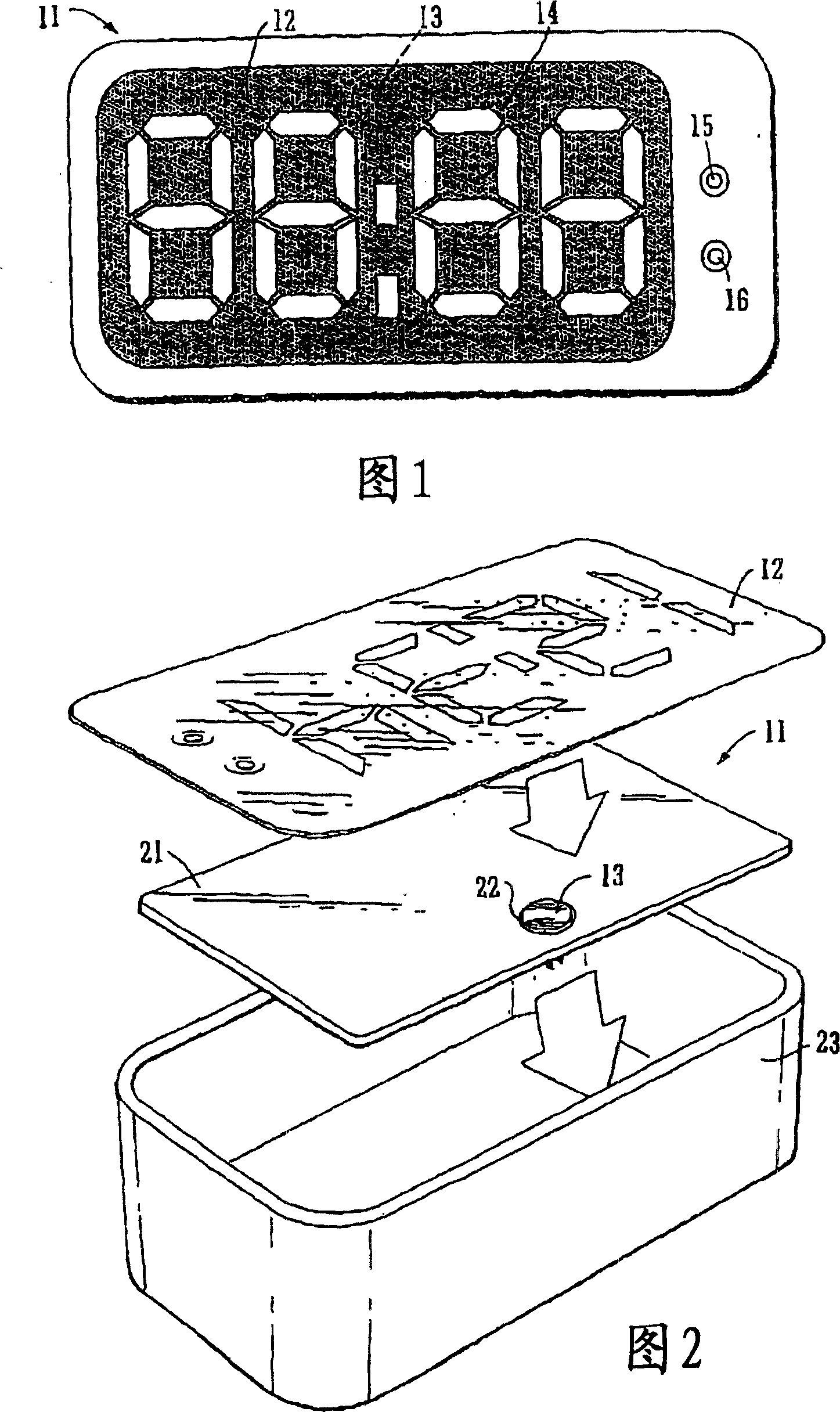
[0026] Figure 1 is a typical configuration of a simple clock type product. It is a clock (11) in which the time is indicated by a standard 7-segment digital display (12). A light sensor (13) is mounted behind the front-facing display, hidden behind one or more layers (eg, optical filters or dielectric layers) in the display structure, but not obscured by the display segment (14). Buttons (15) and (16) allow the user to control the apparent brightness of the display.

[0027] In the "exploded" view of Figure 2, the display (12) is mounted in front of the printed circuit board (PCB; 12). The components of the PCB are not shown except for the sensor (13), which is mounted on the reverse side of the circuit board (21) and is visible through the aperture (22) therein. In use, the display (12) and PCB 21 are mounted within a simple box-like container (23).

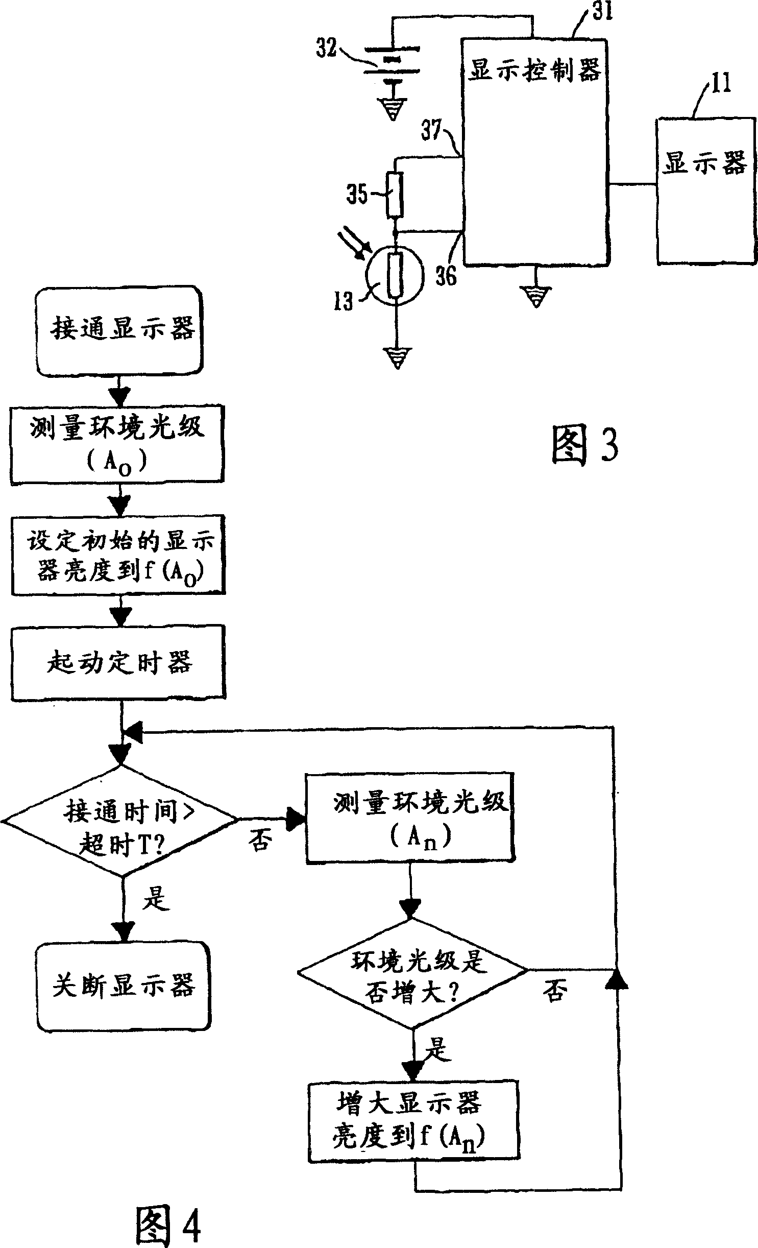
[0028] Fig. 3 shows a circuit diagram using a photoresistor (13) as an ambient light sensor.

[0029] The relevant compone...


PUM


Abstract

A light-emitting display having display areas (14), which may be lit or unlit, comprising a sensor (13) for ambient light, in which the display is arranged to use an output of the sensor (13) to modify the brightness of the display areas (14) when lit in dependence upon the ambient tight conditions, the sensor being hidden behind an unlightable section of the display. The display is particularly advantageously an electroluminescent display.

Description

technical field [0001] The present invention relates to improved displays, and more particularly to displays such as electroluminescent displays which utilize ambient light sensors to adjust the brightness and contrast of the display in response to ambient light conditions. Background technique [0002] Certain materials are electroluminescent, ie, the material emits a glow when an electric field is applied to the electroluminescent material. The first known electroluminescent materials were inorganic particulate substances, such as zinc sulfide, while more recently discovered electroluminescent materials include: a variety of small molecule organic emitters, such as organic LEDs (OLEDs), and some plastics, For example, synthetic organic polymers known as light emitting polymers (LEPs). We still use inorganic particles in doped and encapsulated form, especially mixed in binders and applied to substrate surfaces in relatively thick layers; LEP can be used as particle materia...

Claims


Application Information

Patent Timeline
IPC IPC(8): G09G3/32G09G3/04G09G3/12G09G3/18
CPCG09G3/04G09G2320/0626G09G3/12G09G3/18G01J1/4204G09G2360/144
Inventor 克里斯托弗·J.·N.·弗莱尔理查德·G.·布莱克斯利
Owner PELIKON
Why Eureka
Try Eureka