Short arc discharge lamp

A discharge lamp and short-arc technology, applied in the field of short-arc discharge lamps, can solve the problems of decreased lamp illumination, increased processing cost and processing time, peeling and the like

Inactive Publication Date: 2007-04-04
ORC MFG
View PDF5 Cites 8 Cited by
  • Summary
  • Abstract
  • Description
  • Claims
  • Application Information

AI Technical Summary

Problems solved by technology

In order to prevent the lamp illuminance drop caused by the blackening substance, in the method of providing a substance called a getter that absorbs the blackening substance in the electrode, there are problems such as the following: When the getter is provided on the anode side, Peeling due to high temperature, when a getter is installed on the cathode side, discharge occurs between the getter and the electrode
In the method of suppressing blackening substances, only the absolute amount of blackening substances generated during lamp lighting is reduced, but there is no change in the adhesion of blackening substances to the surface emitting light, and the decrease in illuminance cannot be prevented.
In the method of providing a getter, a through hole, a tungsten sintered layer, or a confinement plate in the electrode, processing cost and processing time increase

Method used


Image

  • Short arc discharge lamp
  • Short arc discharge lamp
  • Short arc discharge lamp

Examples


Embodiment Construction

[0031] Hereinafter, the best mode for carrying out the present invention will be described in detail with reference to FIGS. 1 to 5 .

[0032] 【Example】

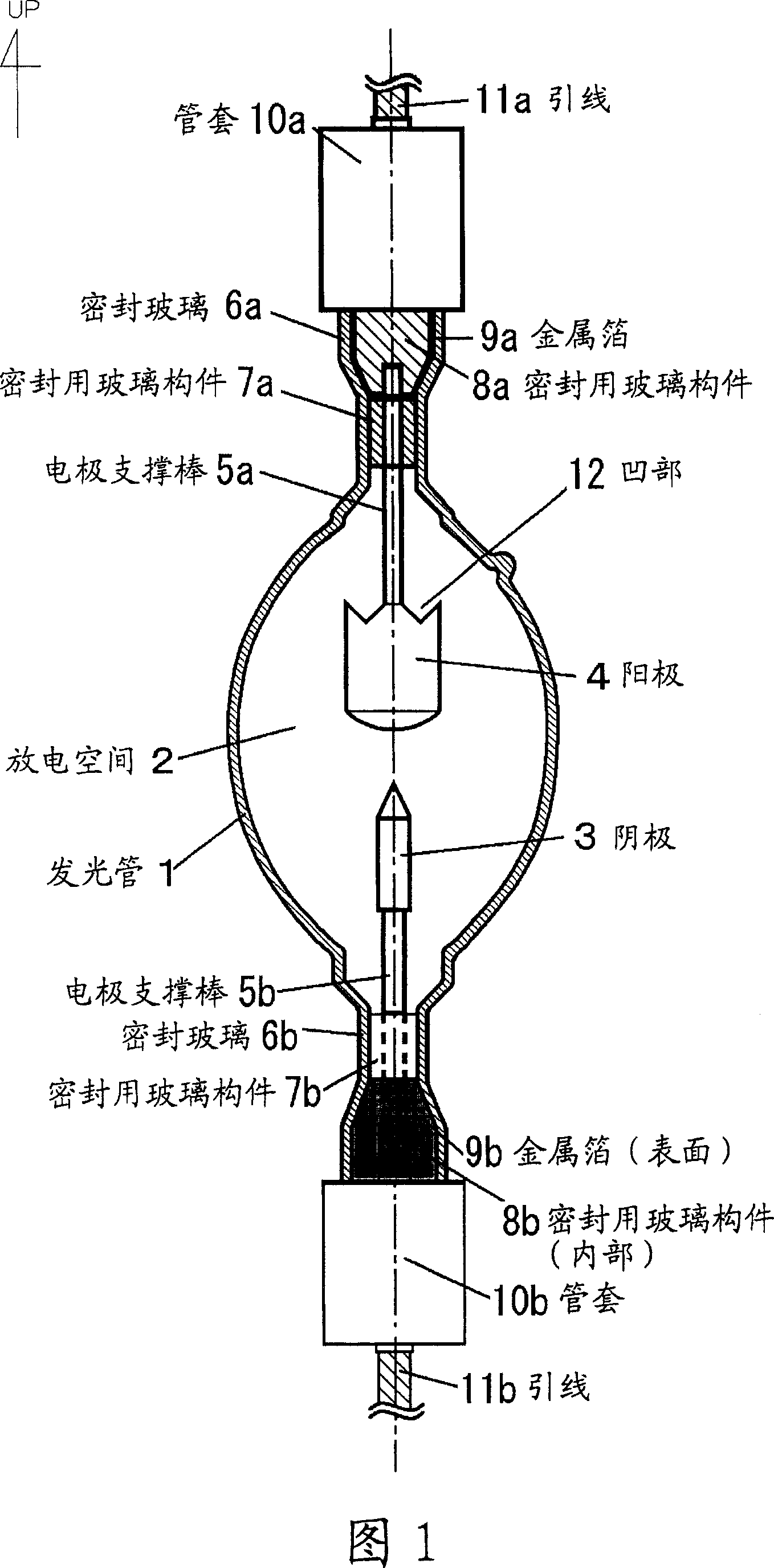
[0033] An embodiment of the present invention is a short-arc discharge lamp in which a concavity with a concave, U-shaped, レ-shaped, or V-shaped cross-sectional shape is provided on the end surface of the light-emitting tube that becomes the upper electrode at the time of lighting. .

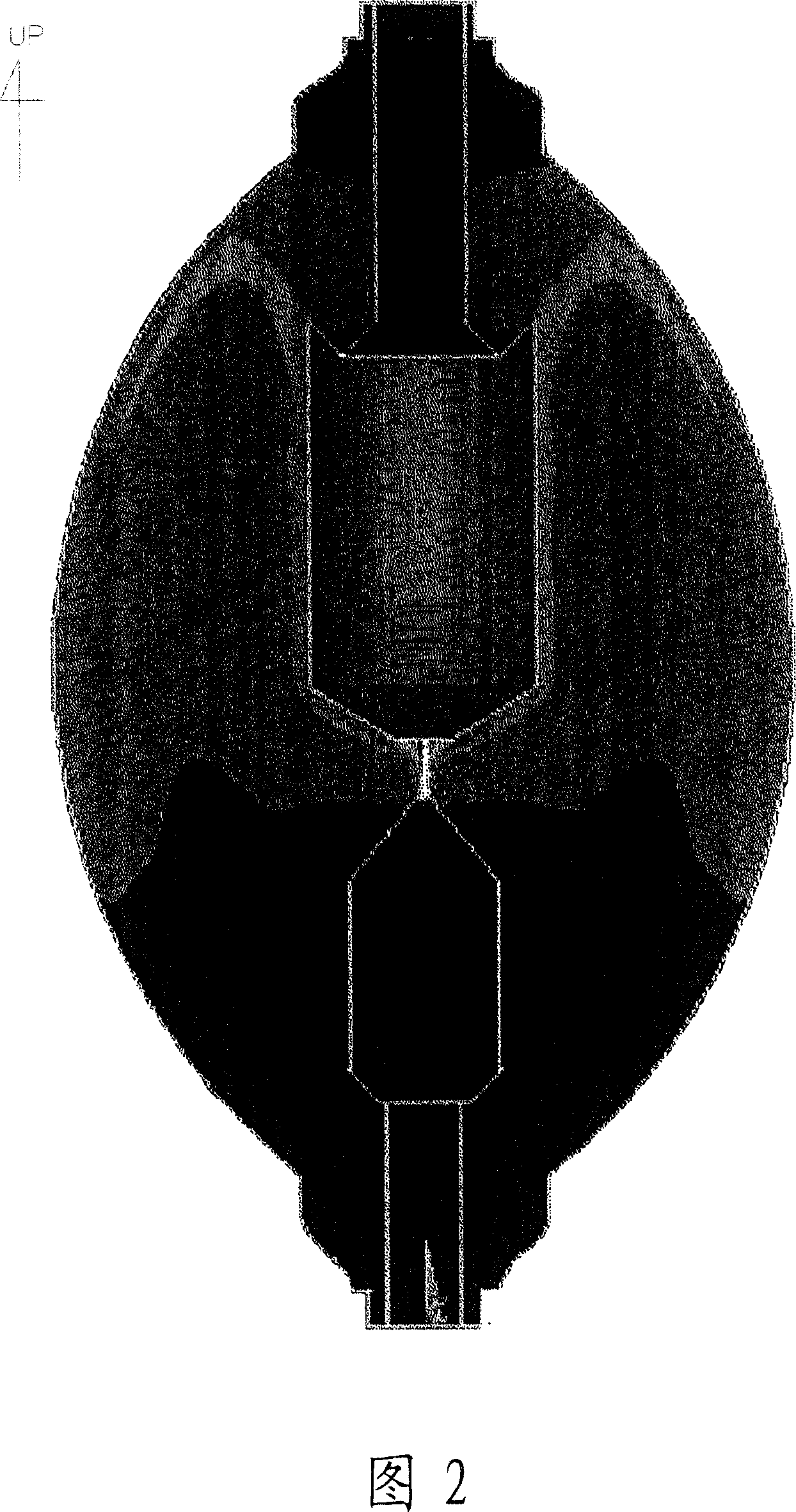
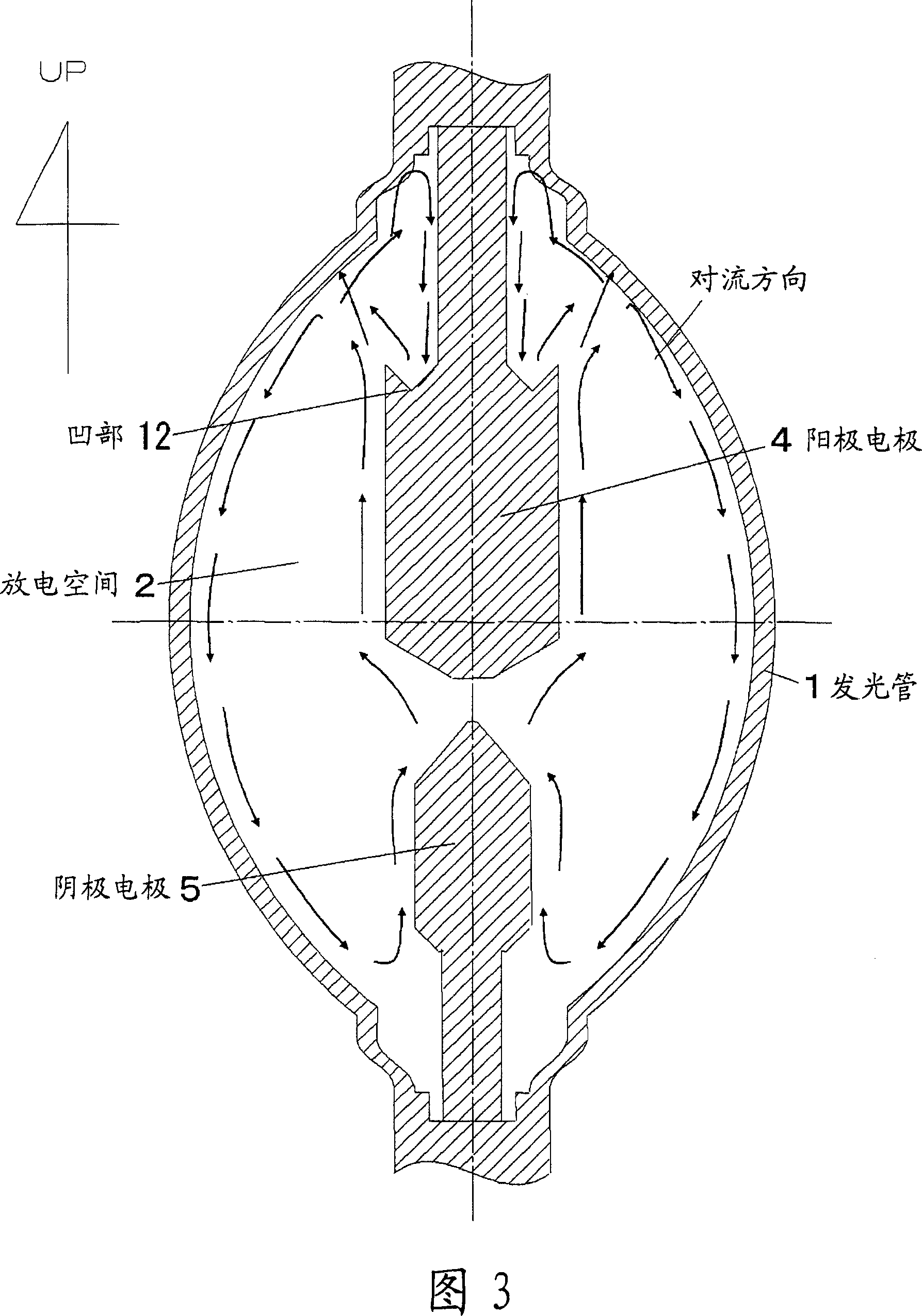
[0034] Fig. 1 is a conceptual diagram of a short-arc discharge lamp in an embodiment of the present invention. Fig. 2 is a graph showing the results of a convection simulation of the main air flow of a short-arc type lamp. Fig. 3 is a schematic diagram showing the calculated convective direction of a short-arc type discharge lamp. 4 and 5 are diagrams showing examples of the shape of the rear end surface of the anode of the short-arc lamp.

[0035]In FIGS. 1 to 5 , the arc tube 1 is a bulb of a short-arc discharge lamp. The discharge spac...


PUM


Abstract

The present invention provides a short arc discharge lamp, to prevent blackened materials from adhering to the optical irradiation surface area of a short arc discharge lamp where a pair of electrodes go up and down at lighting time for avoiding reduced illuminance. A dent (12) is provided at the edge of an arc tube end on the upper positive electrode (4). The cross section of the dent (12) has a concave form, U shape, check-mark shape, or V shape. Through the dent (12), a convective gas from the upper end of an arc tube (1) is forced to recirculate to the upper end of the arc tube (1). A rising current passing through the lateral side of the positive electrode (4) moves towards the upper end of the arc tube (1). An air current combined with the falling current and rising current collides with the inner side near the upper end of the arc tube (1). An air current containing the blackened material components collides with a position greatly shifted from the arc tube surface area required for the optical irradiation, thus to prevent the surface area required for the optical irradiation from being blackened.

Description

technical field [0001] The present invention relates to a short-arc discharge lamp, and more particularly, to a short-arc discharge lamp used as a light source in the exposure process of semiconductor or liquid crystal manufacturing. Background technique [0002] In the exposure process in the manufacturing process of a semiconductor element or a liquid crystal display device, etc., high illuminance is required for the short-arc discharge lamp used as a light source. Such a short-arc discharge lamp (hereinafter simply referred to as a lamp) generally uses a lamp with a switching power of 1 kW or more, and the temperature and internal pressure when the lamp is turned on are quite high. As one method for increasing the illuminance, there is a method of enclosing more mercury, a rare gas, etc., and improving the lamp luminous efficiency in the ultraviolet region. In such a short-arc type discharge lamp, due to the generation of high-temperature plasma caused by arc discharge, ...

Claims


Application Information

Patent Timeline
Patent Type & Authority Applications(China)
IPC IPC(8): H01J61/26
Inventor 岩间裕一朗加濑征彦
Owner ORC MFG
Why Eureka
Try Eureka