Controller and control for electronic ballast resistor and high-performance gas discharging light

A technology for electronic ballasts and gas discharge lamps, which is applied in the use of gas discharge lamps, lighting devices, electrical components, etc., can solve the problems of large electromagnetic interference, many links, and increased tube pressure.

Inactive Publication Date: 2007-04-04
NORTH CHINA UNIVERSITY OF TECHNOLOGY
View PDF3 Cites 4 Cited by
  • Summary
  • Abstract
  • Description
  • Claims
  • Application Information

AI Technical Summary

Problems solved by technology

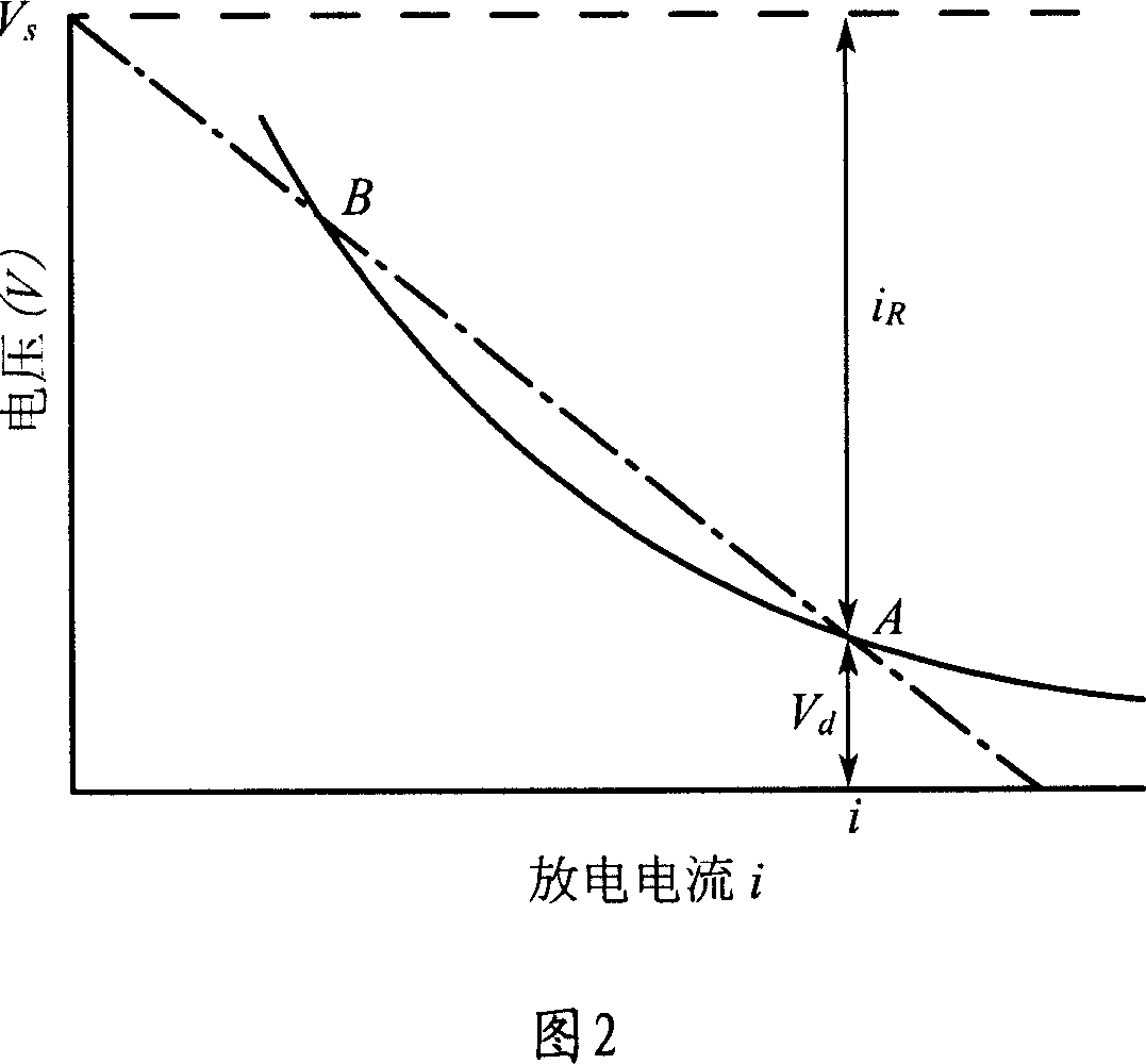
[0022] 2. For the same type of HID lamp produced by different manufacturers, the distance between the two electrodes will be quite different, that is, the distance between the two electrodes of the same type of lamp produced by the same manufacturer also has a certain dispersion
[0023] 3. As the use time of the lamp increases, the distance between the two electrodes increases continuously, so the tube pressure also increases
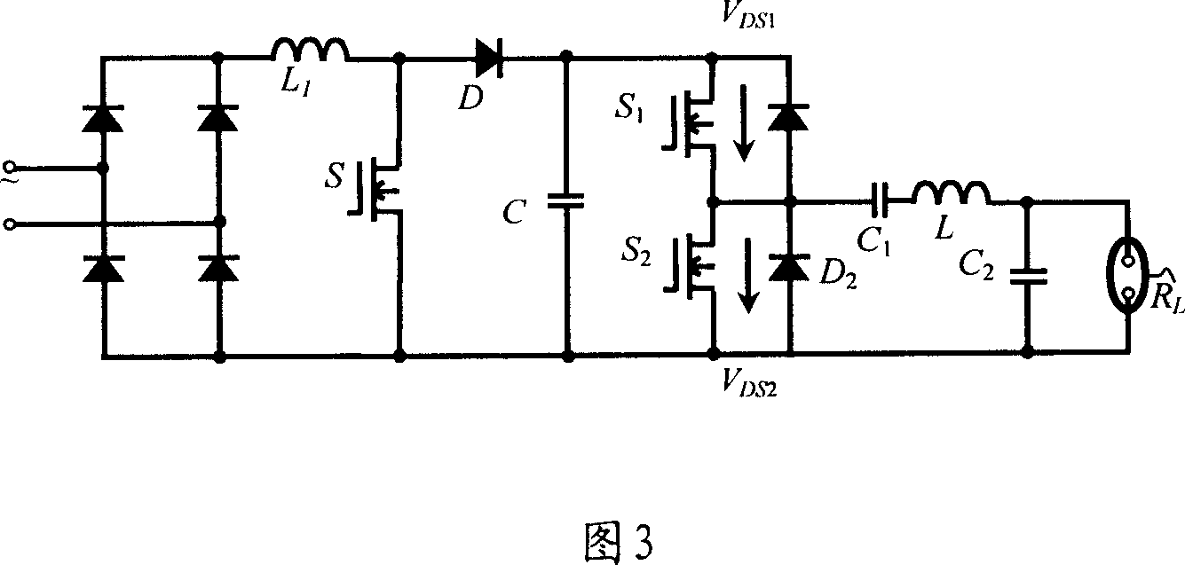
The active power factor correction circuit is used to improve the power factor of the input terminal, reduce the high-order harmonics of the input current, and provide a constant voltage of about 400V for the BUCK converter; the BUCK converter acts as a current and power regulator to make its output current , The voltage and power match the electrical characteristics of the lamp; the inverter converts the output of the BUCK converter into the AC signal required by the HID lamp, so this electronic ballast has the following disadvantages: many links, resulting in low efficiency, electromagnetic Great interference
The main disadvantages of electronic ballasts using this intermediate frequency modulation technology include: the control circuit is complicated, and it cannot be generally applied to HID lamps of various specifications, types and models
The main disadvantages of electronic ballasts using this high-frequency modulation technology are: low efficiency, large electromagnetic interference, and it is difficult to meet the requirements of relevant international and national standards
[0028] Currently commonly used control technology, when the output power of the electronic ballast is small, this control technology can basically meet the requirements of the high-intensity discharge lamp and make the system work stably, but the experimental results show that when the output power of the electronic ballast is large , this control technology cannot meet the requirements of high-intensity discharge lamps and the system is difficult to work stably

Method used


Image

  • Controller and control for electronic ballast resistor and high-performance gas discharging light
  • Controller and control for electronic ballast resistor and high-performance gas discharging light
  • Controller and control for electronic ballast resistor and high-performance gas discharging light

Examples


Embodiment 3

[0148] A control method based on the high-intensity discharge lamp control device based on the above-mentioned electronic ballast, comprising:

[0149] The first step, the control circuit drives the electronic ballast through the drive circuit according to the working status of the electronic ballast and the high-intensity gas discharge lamp collected by the signal acquisition circuit; it is specifically divided into the following steps:

[0150] 1. The signal acquisition circuit collects the information of the working status of the electronic ballast and the high-intensity gas discharge lamp, and outputs the control signal to the selection status controller and the status controller group; specifically, it can be divided into the following steps:

[0151] (1), the voltage processing circuit of the signal acquisition circuit collects the high-frequency AC voltage signal U of the high-intensity gas discharge lamp R After processing, it becomes one and U R Approximate DC voltag...


PUM


Abstract

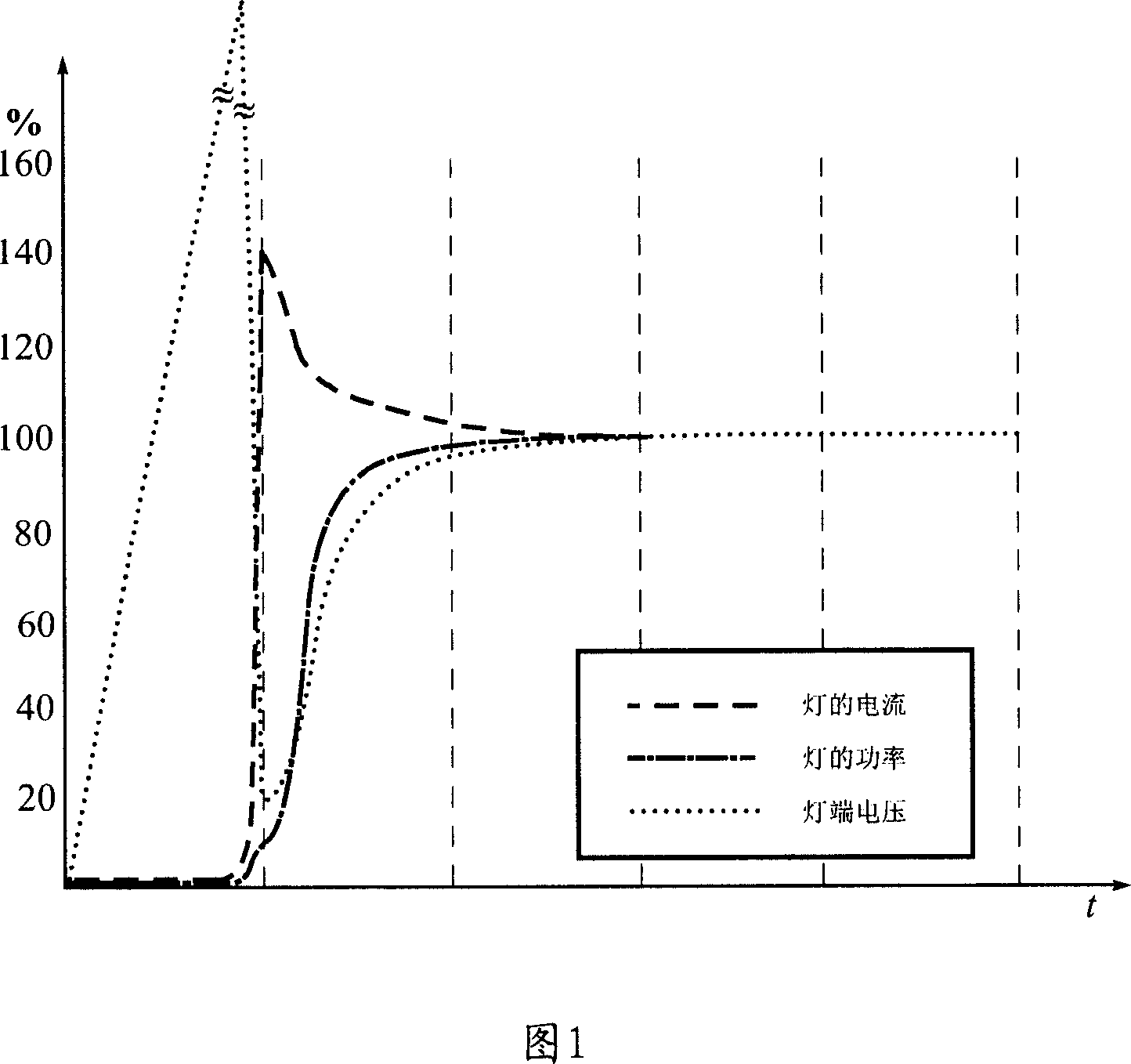
The invention provides the different control approaches in non-triggering stage, startup stage and steady-state stage for high-strength gas-discharging lamp. In non-triggering stage, to adapt the electronic ballast to the dispersity of triggering voltage of high strength gas-discharging lamp, a automatic scan is used t o gradually increase the triggering voltage until the high strength gas discharging lamp is triggered. In start up stage, a real-time control approach is used. In steady-state stage, to adapt the parameter dispersity of the high strength gas discharging lamp, a constant power control approach is used.

Description

technical field [0001] The present invention relates to the field of electronic equipment and its control technology, in particular to an electronic ballast and a high-intensity gas discharge lamp control device and method in the field of lighting technology and the field of electric energy control and conversion technology. Background technique [0002] High-intensity gas discharge lamps (including high-pressure sodium lamps and metal halide lamps, hereinafter referred to as HID lamps) are an important member of electric light source products. Compared with incandescent lamps, HID lamps have greatly improved their luminous efficiency. However, it is not so easy to maintain the stability and consistency of light color quality. HID lamps have a wide range of applications, such as store lighting, display lighting, commercial street lighting, billboard lighting, and film and television lighting. Due to their large luminous flux and excellent light color performance, they can cr...

Claims


Application Information

Patent Timeline
Patent Type & Authority Applications(China)
IPC IPC(8): H05B41/28H05B41/288
CPCY02B20/204Y02B20/00
Inventor 张卫平
Owner NORTH CHINA UNIVERSITY OF TECHNOLOGY
Why Eureka
Try Eureka