

RFID tag device
一种电子标签、器件的技术,应用在无线射频识别电子标签器件领域,能够解决输出电压低、发射输出(转换效率低、接收功率损失等问题
- Summary
- Abstract
- Description
- Claims
- Application Information
AI Technical Summary
Problems solved by technology
Method used
Image

Examples
Embodiment approach 1
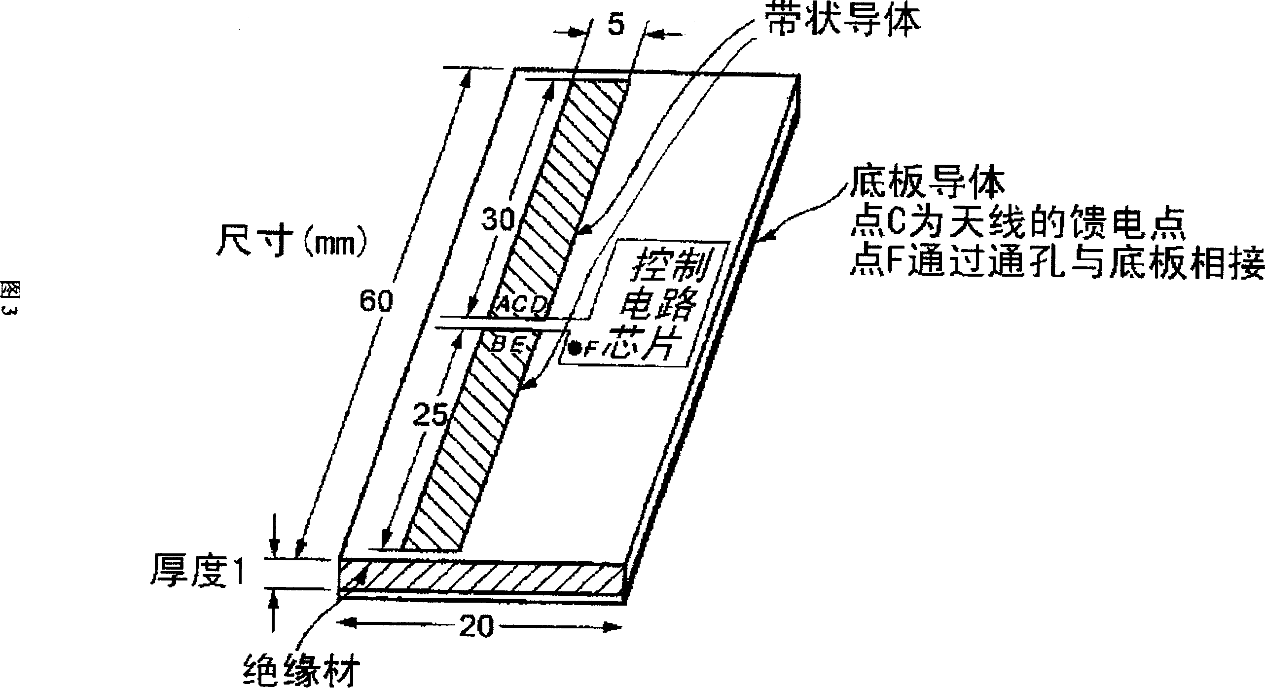
[0089] Fig. 3 shows the basic structure of the RFID electronic tag of the present invention. In this figure, the antenna of the RFID electronic tag device is composed of a bottom plate conductor, an insulating layer and a two-part strip conductor. The RFID electronic tag device shown in this figure uses the 2.45GHz frequency band, and all specific dimensions are in mm. In addition, the split point in the two-split strip conductor deviates a little from the equal split point in the longitudinal direction. According to the effect presented by this feature, the signal receiving efficiency of the antenna can be maximized.
[0090] FIG. 4 shows the contents of the control circuit chip shown in FIG. 3 and the state in which the two-divided strip conductor and the control circuit are connected.
[0091] In Figure 4, six points A, B, C, D, E, and F are connected between the control circuit chip and the antenna. The PIN diodes D7 and D8 used for impedance modulation are connected bet...
Embodiment approach 2
[0108] (Positioning method for moving objects without RFID electronic tags)
[0109] The RFID electronic tag of the present invention has the characteristics of having no power supply and being capable of long-distance communication, and this characteristic is utilized here.
[0110] As shown in Figure 6, on the premise that the positions of electronic tags #1 and #4 and interrogators #1 and #2 are known, the position of the mobile body can be estimated according to the information of the path blocked by the mobile body.
[0111] In this case, it is also possible to time divide the CW output from the interrogator into fm1=fm2, fs1=fs2=fs3=fs4, and make the response from the electronic tag an anti-collision system.
[0112] Furthermore, it is also possible to make the CW output from the interrogator continuously output as fm1≠fm2, fs1=fs2=fs3=fs4, and make the response from the electronic tag an anti-collision system.
[0113] Furthermore, it is also possible to make a system ...
Embodiment approach 3
[0115] (Positioning method for mobile objects equipped with RFID)
[0116] The RFID electronic tag of the present invention has the characteristics of having no power supply and being capable of long-distance communication, and this characteristic is utilized here.
[0117] As shown in Figures 22 and 23, multiple receiving antennas are used on the host, and transmit cw signals equal to or greater than two frequencies, and then detect the phase difference of the response signal from the RFID electronic tag to estimate the three-dimensionality of the RFID electronic tag Location.
[0118] The host structure is revealed in Figure 7. The Fourier transform unit performs time-series Fourier integration on the data of Re and Im of antenna #1 and even antenna #4, and calculates the frequency spectrum phase of frequency Δ. At this time, the phase difference caused by the switching time difference between each antenna cable and the down converter and the selection SW is corrected and ...
PUM
 Abstract
Description
Claims
Application Information