Controlled cooling heat treating process and its device for bainite ductile iron

A bainitic ductile, controlled cooling technology, applied in heat treatment furnaces, heat treatment equipment, quenching devices, etc., can solve the limitations of large-scale promotion and application of ductile iron wear parts, high production cost of bainitic ductile iron, easy to form Carbide or oxide and other problems, to achieve the effect of low cost, simple structure and improved hardenability

Active Publication Date: 2007-04-11
YUNNAN KUNGANG WEAR RESISTANT MATERIAL SCI
View PDF0 Cites 9 Cited by
  • Summary
  • Abstract
  • Description
  • Claims
  • Application Information

AI Technical Summary

Problems solved by technology

However, the isothermal quenching process has complex process, long process, large energy consumption, and the quenching medium is easy to pollute the environment, and certain Cu, Mo, Ni alloy elements need to be added to improve hardenability, so that the production cost of bainitic ductile iron is high and the quality is low. Instability and other shortcomings; (2) Obtain bainite ductile iron by alloying under air-cooling or as-cast conditions, that is, by adding a certain amount of alloying elements such as Ni, Mo, B, etc., change the shape of the CCT curve of ductile iron, delay Its high-temperature transformation enables the supercooled austenite to continuously pass through the middle temperature zone of bainite transformation at an appropriate cooling rate, thereby obtaining a bainite / martensite multiphase structure under air-cooling conditions
Compared with the traditional austempering process for obtaining bainite / martensite multiphase structure, this process has the advantages of saving energy, shortening the production cycle, reducing pollution, etc., but at the same time, it has insufficient hardenability of large sections and alloy elements After adding, it is easy to form carbides or oxides, which will lead to disadvantages such as increased material costs
The deficiencies and limitations of the above-mentioned heat treatment process have limited the large-scale promotion and application of ductile iron wear parts with bainite multiphase structure, and it is difficult to meet market needs.

Method used


Image

  • Controlled cooling heat treating process and its device for bainite ductile iron
  • Controlled cooling heat treating process and its device for bainite ductile iron

Examples


Embodiment Construction

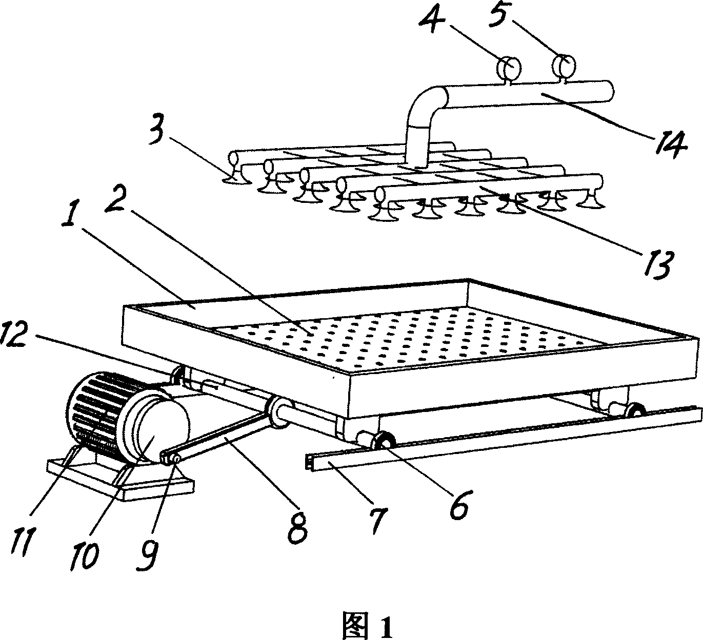
[0016] The atomizing spray device of the present invention will be further described in conjunction with accompanying drawing 1 below.

[0017] Among Fig. 1, drain hole 2 is provided on the bottom plate of workpiece platform 1, two symmetrical wheel shafts 12 are installed below workbench 1, roller 6 is installed at the two ends of each wheel shaft 12, and roller 6 is placed on guide rail 7, so that on guide rail 7, wherein the wheel shaft 12 is connected with one end of the connecting rod 8, the other end of the connecting rod 8 is fixed on the eccentric shaft 9, and the eccentric shaft 9 is fixed on the runner 10 connected with the output shaft of the motor 11, so as to pass through the runner 10 The eccentric shaft 9 and the connecting rod 8 change the circular motion into a linear motion, so that the workbench 1 moves back and forth under the drive of the motor 11; the top of the workbench 1 is provided with a pipe group 13, and each pipe is equipped with a plurality of noz...


PUM

PropertyMeasurementUnit
hardnessaaaaaaaaaa

Abstract

The present invention relates to one kind of controlled cooling heat treatment process and apparatus for bainite ductile iron. The process includes atomizing water as quenching medium in the controlled cooling heat treatment apparatus to spray ductile iron workpiece after austenization at controlled water flow pressure to obtain sufficient cooling speed to avoid pearlite transformation in the high temperature area and to cool to bainite transforming temperature fast; passing through the medium temperature area at lowest cooling speed for bainite transformation; and chilling after bainite transformation to below martensitic transformation point; so as to obtain complex bainite/martensite structure. The present invention has low cost and reduced environmental pollution, and is suitable for large scale production.

Description

technical field [0001] The invention relates to a heat treatment process of ductile iron and a device thereof, in particular to a controlled cooling heat treatment process of bainite ductile iron and a device thereof, belonging to the field of heat treatment processes of metal materials. Background technique [0002] Due to its excellent wear resistance and excellent comprehensive mechanical properties, the ductile cast iron with bainite / martensitic multiphase structure has become an ideal material for abrasive wear resistance, and has excellent wear resistance, impact resistance, high strength, high toughness and It has been applied in many occasions such as fatigue resistance. For example, as a grinding ball used in a ball mill, etc. At present, the main ways to obtain bainite structure in ductile iron are: (1) Obtained by austempering process, that is, the workpiece is austenitized and quenched to the isothermal transformation in the lower bainite temperature region, and...

Claims


Application Information

Patent Timeline
Patent Type & Authority Applications(China)
IPC IPC(8): C21D9/00C21D1/667C21D1/18
Inventor 周荣蒋业华胡国忠张玉勤周荣锋黎振华卢德宏
Owner YUNNAN KUNGANG WEAR RESISTANT MATERIAL SCI
Why Eureka
Try Eureka