Integrated permanent magnet rotor magnetic suspension high speed motor

A permanent magnet rotor and high-speed motor technology, applied to synchronous motors with stationary armatures and rotating magnets, etc., can solve the problems of low tensile strength of permanent magnets, solve life problems, simplify manufacturing processes, and reduce harmonics. Effects of wave loss and torque ripple

Inactive Publication Date: 2007-04-11
SHENYANG POLYTECHNIC UNIV
View PDF0 Cites 23 Cited by
  • Summary
  • Abstract
  • Description
  • Claims
  • Application Information

AI Technical Summary

Problems solved by technology

However, the speed of high-speed motors is as high as tens of thousands or even hundreds of thousands of revolutions per minute, and the peripheral speed can reach over 200m / s. Tensile stress
The traditional permanent magnet motor structure and design method used for medium and low speed operation is no longer suitable for high speed permanent magnet motor

Method used


Image

  • Integrated permanent magnet rotor magnetic suspension high speed motor
  • Integrated permanent magnet rotor magnetic suspension high speed motor
  • Integrated permanent magnet rotor magnetic suspension high speed motor

Examples


Embodiment

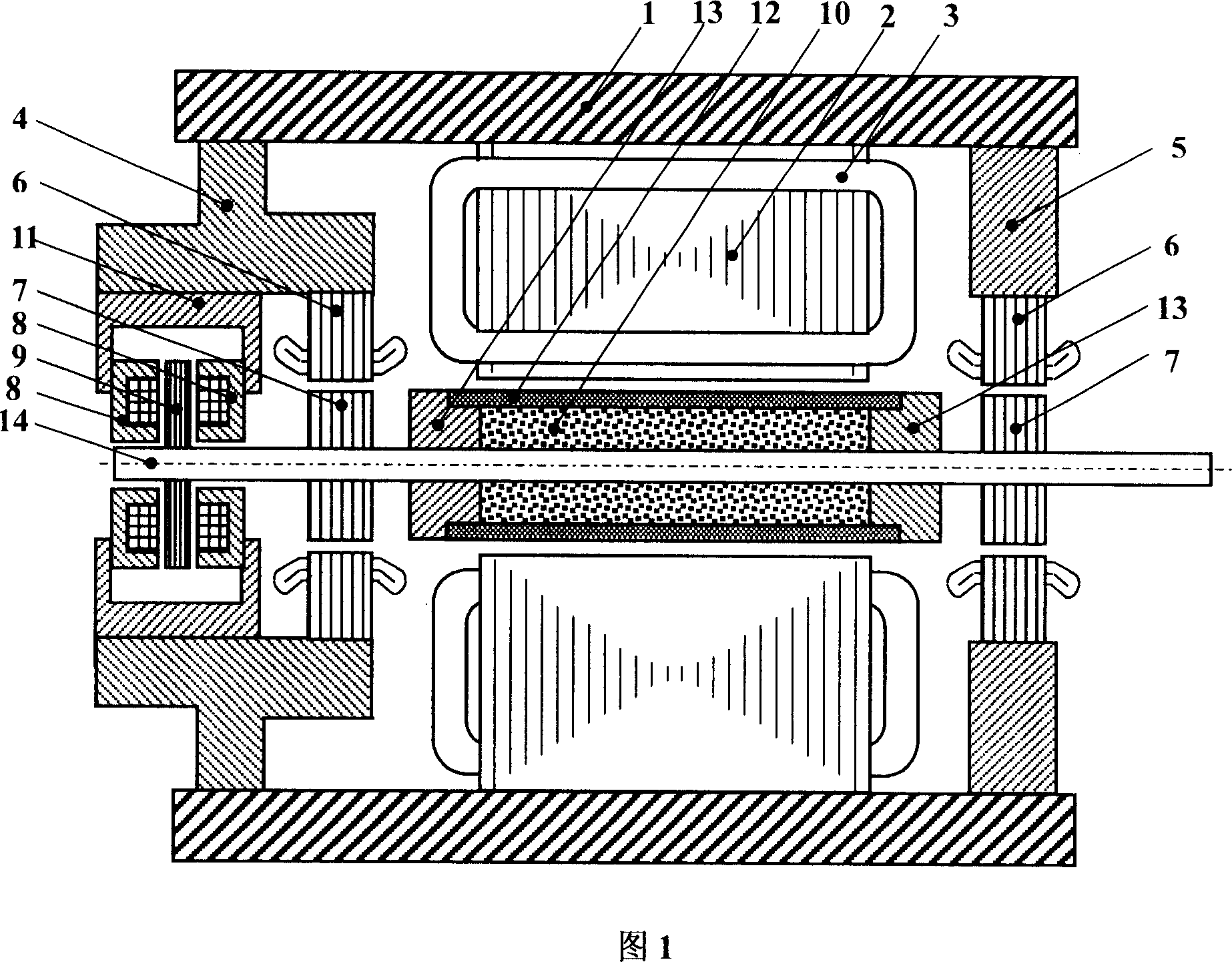
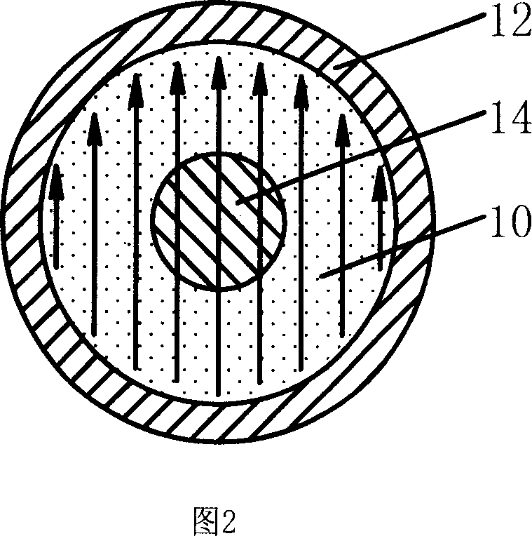
[0021] Embodiment: As shown in Figure 1, the structure of the present invention includes a casing 1, a left end cover 4, a right end cover 5, a stator core 2, a stator winding 3, a permanent magnet rotor, a rotating shaft 14, an axial magnetic suspension bearing and left and right radial Magnetic suspension bearing, a permanent magnet rotor is placed on the motor shaft 14, a stator core 2 is placed around the permanent magnet rotor on the inner wall of the casing 1, and the stator winding 3 is embedded in the slot of the stator core 2; the left end cover 4 and the right end cover 5 are respectively fixed At both ends of the casing 1 on both sides of the stator core 2; a right radial magnetic suspension bearing is placed between the rotating shaft 14 and the right end cover 5; The magnetic suspension bearing, the axial magnetic suspension bearing is placed at the end of the rotating shaft 14, and the other end of the rotating shaft 14 is connected with the driving machine throug...


PUM


Abstract

An integral permanent magnet rotor magnetic suspension high speed motor includes a shell, right and left covers, a stator core, a stator winding, a magnet rotor, a shaft, an axial magnetic suspension bearing and right and left radial magnetic suspension bearings, in which, the magnet rotor is set on the shaft of the motor, the stator core is mounted on the internal wall and surrounding the rotor, the stator winding is inserted in the core tank, the right and left covers are fixed at either end of the shell at both sides of the stator core, a right radial magnetic suspension bearing is set between the shaft and the right cover, the left radial suspension bearing and the axial bearing are mounted between the shaft and the left cover and the axial bearing is set at the end of the shaft, the other end of the shaft is connected with the drive device by a coupling and the magnet rotor is an integer structure.

Description

technical field [0001] The invention belongs to the technical field of motors, and relates to a high-speed motor with integral permanent magnet rotor magnetic levitation. Especially suitable for high-speed motors and high-speed generators. Background technique [0002] Due to the high speed and high power density of high-speed motors, its geometric size is much smaller than that of low- and medium-speed motors with the same output power, which can effectively save materials; high-speed motors can be directly connected to prime movers or loads, eliminating the need for traditional mechanical transmissions. It can reduce noise and improve the efficiency of the transmission system. The application fields of high-speed motors are becoming more and more extensive, such as high-speed grinding machines and other processing machine tools, high-speed flywheel energy storage systems, high-speed centrifugal compressors and blowers used in natural gas transmission and sewage treatment,...

Claims


Application Information

Patent Timeline
Patent Type & Authority Applications(China)
IPC IPC(8): H02K21/14
Inventor 王凤翔张凤阁宗鸣王继强白浩然邢军强
Owner SHENYANG POLYTECHNIC UNIV
Why Eureka
Try Eureka