Water taking gallery of self flow type for underground reservoir

An underground reservoir and self-flowing technology, which is applied in water supply devices, drinking water devices, buildings, etc., can solve the problems of limited water collection flow and water intake range, huge one-time investment, and small underground reservoir scale, which is conducive to automatic control , reduce the annual operating costs, the effect of a large amount of water intake

Inactive Publication Date: 2007-04-18
新疆水利水电规划设计管理局
View PDF0 Cites 20 Cited by
  • Summary
  • Abstract
  • Description
  • Claims
  • Application Information

AI Technical Summary

Problems solved by technology

At present, in order to solve the problem of storage and shortage of water resources in the small and medium-sized watersheds of inland rivers in arid areas, the construction of surface reservoirs, technical solutions of electromechanical wells and water intake corridors are only used as auxiliary measures for water resource storage. Although the technical method of the electromechanical well group has the advantages of small one-time investment and convenient control, it needs to use power to lift the water in the well pipe to the ground, the operation cost is high, and the water output of a single well is small. It is conducive to the concentration of water, but it is difficult to input water into the main canal to regulate and store water resources. The technical method of the underground reservoir formed by the existing water collection corridor at the alluvial fan in the front of the mountain has very limited water collection flow and water intake range. The size of the formed underground reservoir is small and cannot effectively replace the function of the surface reservoir. For example, the largest scale of the Kaner well in Xinjiang is 2m 3 / s, the water collection corridor is long, the flow cannot be controlled, and it is difficult to implement it below the sandy gravel aquifer. The existing radial shaft type water collection wells are divided into arrays, and the scale of a single well is generally 0.5m 3 Therefore, although the problems of "dams and the environment" caused by surface reservoirs are very prominent, the one-time investment is huge, and the economy is poor, it is still commonly used in small and medium-sized watersheds of inland rivers in arid areas. storage project mode

Method used


Image

  • Water taking gallery of self flow type for underground reservoir
  • Water taking gallery of self flow type for underground reservoir
  • Water taking gallery of self flow type for underground reservoir

Examples


Embodiment Construction

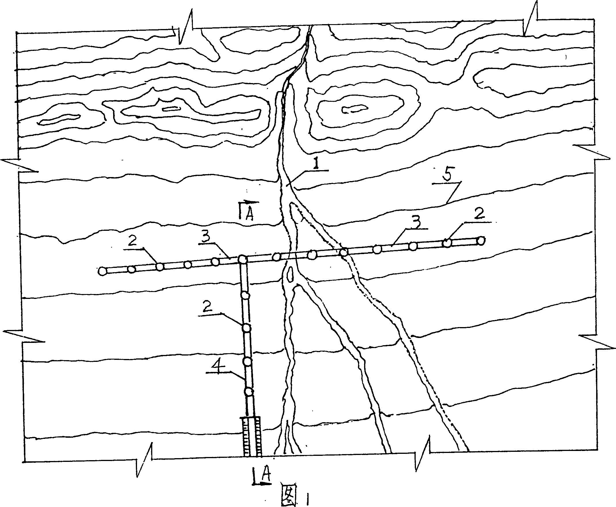
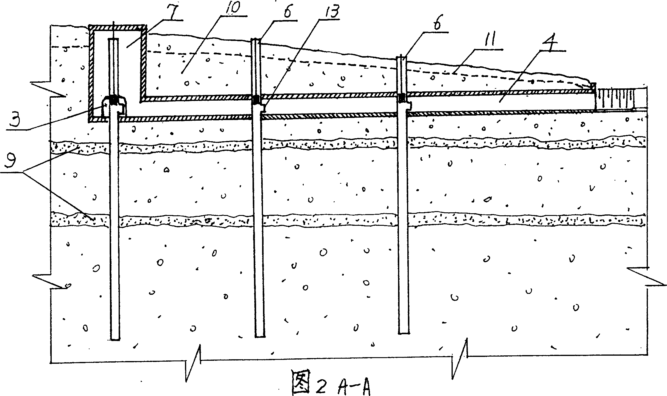
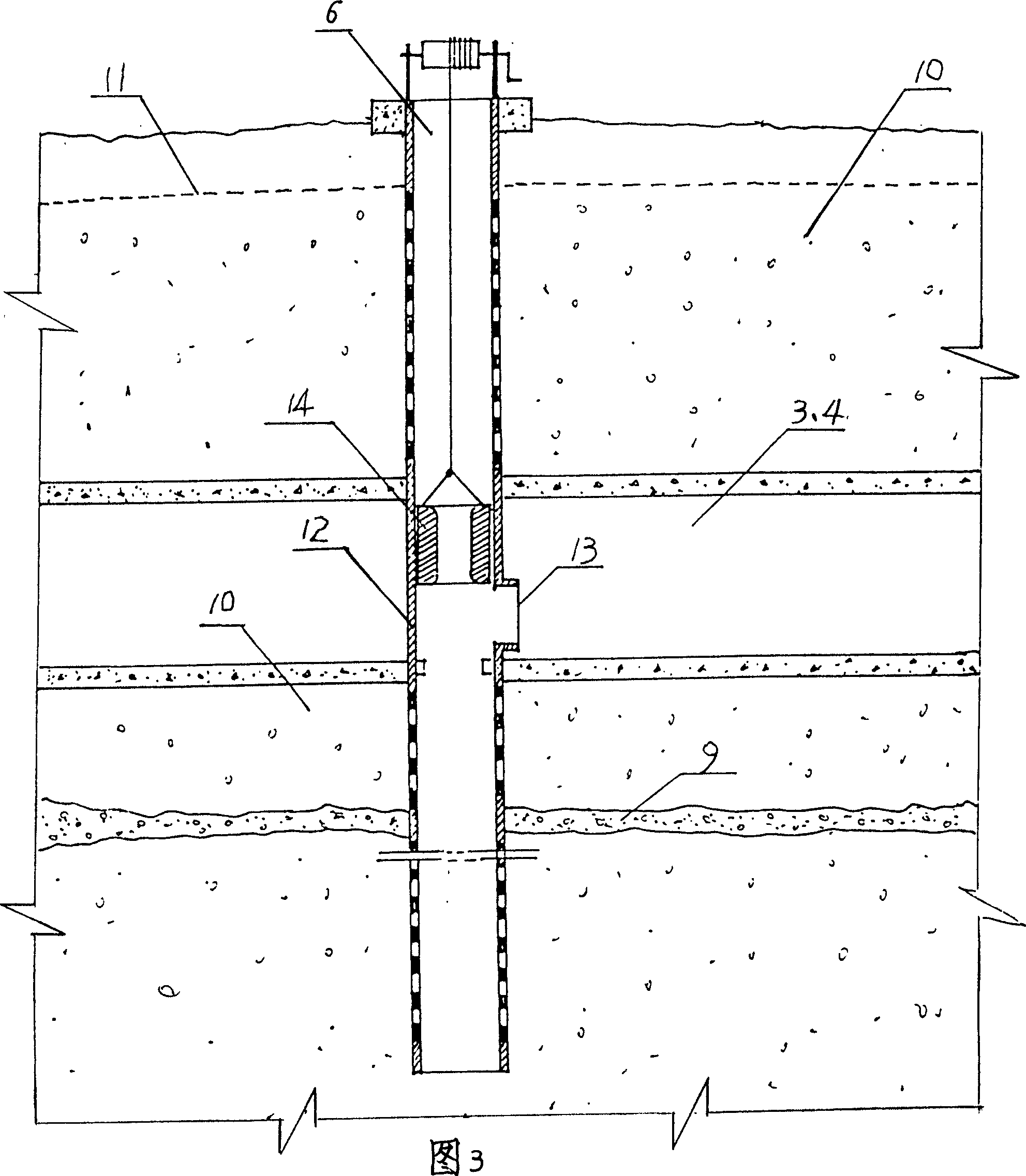
[0021] A water intake corridor of a self-flowing underground reservoir, as shown in Figure 1 and Figure 2, is a typical form of the lower edge of the alluvial-diluvial fan of the small and medium-sized watersheds arranged in the surface runoff dissipation area of ​​the small and medium-sized watersheds of inland rivers in arid areas according to the present invention. 1 After exiting the mountain pass, it is perpendicular to the ground contour line 5 and flows downstream, where the groundwater level line 11 at the lower edge of the alluvial fan is generally 2-30m away from the ground. In the sand and gravel aquifer 10, 2 groups of vertical water intake wells are set according to engineering requirements. The vertical water intake wells 2 can be machine-well type water intake wells 6 or hybrid type water intake wells 7 or radial shaft type water intake wells 8, and are arranged at the groundwater level line 11. The following catchment tunnel 3 and diversion tunnel 4 connect the ...


PUM


Abstract

This invention relates to a device in hydraulic engineering groundwater extraction, especially a spontaneity underground reservoir of water corridor. There is vertical well in sand stone. Collecting tunnel and diversion tunnel located in the groundwater below the water makes the vertical wells connect from one another. The direction of diversion tunnel is the same to the terrain slope. The diversion tunnel makes the water of vertical well out of the ground. This invention can replace small river valley emerges surface reservoir functions, storing basin of water, so that the groundwater basin rational allocate its resources, its quantity, water wide range of low-cost water, reducing water evaporation. This invention can directly get water in deep coverage river bed, and is appropriate to get water in mountain underground water reservoir.

Description

technical field [0001] The invention relates to a method or device for drawing groundwater in water conservancy projects, in particular to a water intake corridor for self-flowing underground reservoirs suitable for buildings in deep-covered river valleys and submerged overflow zones in arid areas. Background technique [0002] According to the research results of the 21st century water resources strategy in the United States, underground reservoirs are the most important means of regulating water resources in the 21st century. According to research at home and abroad, nature has circulated 12 trillion m of water through the ground for many years. 3 , which is equivalent to 30% of the total surface runoff, while the current water volume adjusted by humans with the help of surface reservoirs is only 2 trillion m 3 , thus it can be seen that there are at least 6 times of water collection capacity underground that is equivalent to surface reservoirs, and it is possible for peo...

Claims


Application Information

Patent Timeline
Patent Type & Authority Applications(China)
IPC IPC(8): E03B3/06
Inventor 裴建生邓铭江董新光
Owner 新疆水利水电规划设计管理局
Why Eureka
Try Eureka