Non-aqueous electrolyte battery

A non-aqueous electrolyte and battery technology, applied in the direction of non-aqueous electrolyte batteries, electrolyte battery manufacturing, secondary batteries, etc., can solve the problems of difficult discharge performance and achieve the effect of reducing deterioration

Inactive Publication Date: 2007-04-25
SANYO ELECTRIC CO LTD +1
View PDF0 Cites 19 Cited by
  • Summary
  • Abstract
  • Description
  • Claims
  • Application Information

AI Technical Summary

Problems solved by technology

However, it is difficult to ensure discharge performance and further satisfy safety requirements, etc.

Method used


Image

  • Non-aqueous electrolyte battery
  • Non-aqueous electrolyte battery

Examples


Embodiment 1

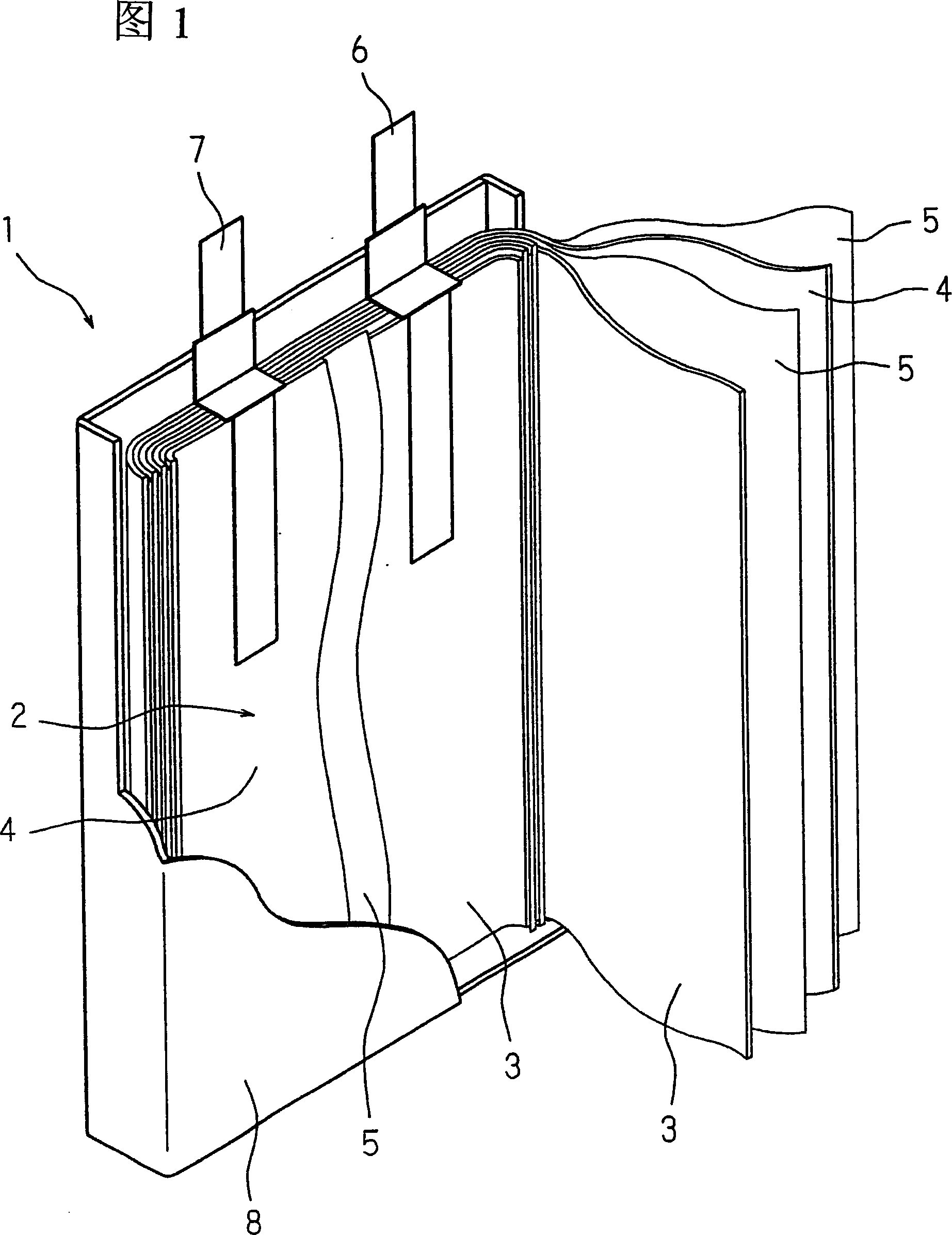
[0021] Fig. 1 shows an exploded perspective view of an example of a nonaqueous electrolyte battery according to the present invention. In Fig. 1, reference numeral 1 is a nonaqueous electrolyte battery (hereinafter referred to as a battery), reference numeral 2 is a generating element (generating element), reference numeral 3 is a positive plate, and reference numeral 4 is a negative plate. Reference numeral 5 is a separator, reference numeral 6 is a positive terminal, reference numeral 7 is a negative terminal, and reference numeral 8 is a battery casing.

[0022] For the positive plate 3, by mixing 94% by mass of lithium cobaltate as an active material, 3% by mass of acetylene black as a conductive agent, and 3% by mass of polyvinylidene fluoride as a binder, and then The mixture was dispersed in N-methyl-2-pyrrolidone (NMP) to prepare a slurry. The slurry was uniformly coated on a 15 μm thick aluminum foil collector and dried, and then film-pressed with a roll press to pre...

Embodiment 2

[0027] A battery similar to that of Example 1 was fabricated except that the adhesive layer polymer had a mass average molecular weight of 800,000.

Embodiment 3

[0029] A battery similar to that of Example 1 was fabricated except that the mass average molecular weight of the adhesive layer polymer was 1,200,000.


PUM

PropertyMeasurementUnit
melting pointaaaaaaaaaa

Abstract

In a non-aqueous electrolyte battery including a generating element having a separator bonded with an adhesive layer between a positive electrode plate and a negative electrode plate, the adhesive layer contains a fluorine-based polymer having a mass average molecular weight of from 500,000 to 1,500,000 and a melting point of from 165° C. to 175° C., and an inorganic-solid filler. The fluorine-based polymer is a polyvinylidene fluoride-based polymer such as a polyvinylidene fluoride homopolymer.

Description

technical field [0001] The present invention relates to a nonaqueous electrolyte battery in which a separator between a positive electrode plate and a negative electrode plate is bonded with an adhesive layer. Background technique [0002] In a polymer electrolyte battery containing a polyelectrolyte in a battery case, for example, between a positive electrode, a negative electrode, and a separator as a separator, leakage of the solution is less likely to occur because the polyelectrolyte enables easy retention of the electrolytic solution. Also, since the polyelectrolyte has a role of bonding the electrodes and the separator, shrinkage of the separator can be reduced when abnormal conditions such as heat generation or overcharging occur, thereby improving safety. [0003] However, after the electrolyte is polymerized, the conductivity of ions tends to decrease and the polarization tends to be greater compared with non-polymerized electrolytes, and especially cycle life char...

Claims


Application Information

Patent Timeline
Patent Type & Authority Applications(China)
IPC IPC(8): H01M10/40H01M4/62H01M2/16H01M10/05H01M10/0525H01M10/0565H01M10/058
CPCY02E60/122H01M10/0525Y02E60/12H01M2/1673H01M2/168H01M2/08Y02E60/10H01M50/461H01M50/46Y02P70/50
Inventor 冈本朋仁
Owner SANYO ELECTRIC CO LTD
Why Eureka
Try Eureka