Ultra slow speed, large torsional moment, short magnetic circuit, speed regulation electric motor of heterotype rotor

A speed-regulating motor, high-torque technology, applied in the magnetic circuit static parts, magnetic circuit rotating parts, magnetic circuit shape/style/structure, etc., can solve the problems of low speed and high torque, and achieve the starting torque The effect of large, material saving and non-ferrous metal material saving

Inactive Publication Date: 2007-05-09
王钢 +2
View PDF3 Cites 6 Cited by
  • Summary
  • Abstract
  • Description
  • Claims
  • Application Information

AI Technical Summary

Problems solved by technology

[0004] In order to achieve the above-mentioned purpose, the present invention breaks through the design mode of the traditional motor, and adopts a speed-regulating motor designed with phase pole independent magnetic circuit, unequal tooth pitch, special-shaped rotor, and short magnetic circuit structure of large and small teeth, which overcomes...

Method used


Image

  • Ultra slow speed, large torsional moment, short magnetic circuit, speed regulation electric motor of heterotype rotor
  • Ultra slow speed, large torsional moment, short magnetic circuit, speed regulation electric motor of heterotype rotor
  • Ultra slow speed, large torsional moment, short magnetic circuit, speed regulation electric motor of heterotype rotor

Examples


Embodiment 1

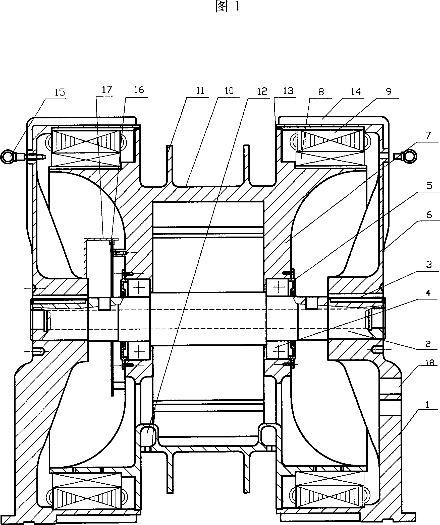
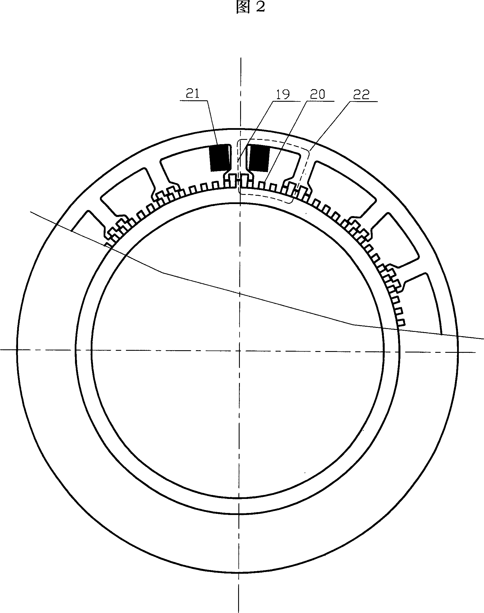
[0047] The special-shaped rotor ultra-low-speed high-torque short-magnetic-circuit speed-regulating motor of the present invention is a drag device designed for "low-speed, high-torque special-shaped motor to drive high-efficiency and low-consumption intelligent pumping unit". The structure is a special-shaped inner rotor ultra-low-speed high-torque short magnetic circuit switch reluctance speed-regulating motor. The special-shaped inner rotor and special-shaped outer stator are casted with cast steel at one time. The maximum outer diameter of the outer stator is ∮1600, and the maximum outer diameter of the inner rotor is ∮1380. With a hollow shaft, the outer stator core adopts a large tooth and three small tooth structure, and the stator and rotor tooth poles adopt "W M Golden combination", that is, four-phase winding 3×16 / 90 or 3×32 / 180, three-phase winding 3×18 / 120. The rated speed of the prototype is 0-20 rpm, the rated torque is greater than 20kNm, and the maximum output p...

Embodiment 2

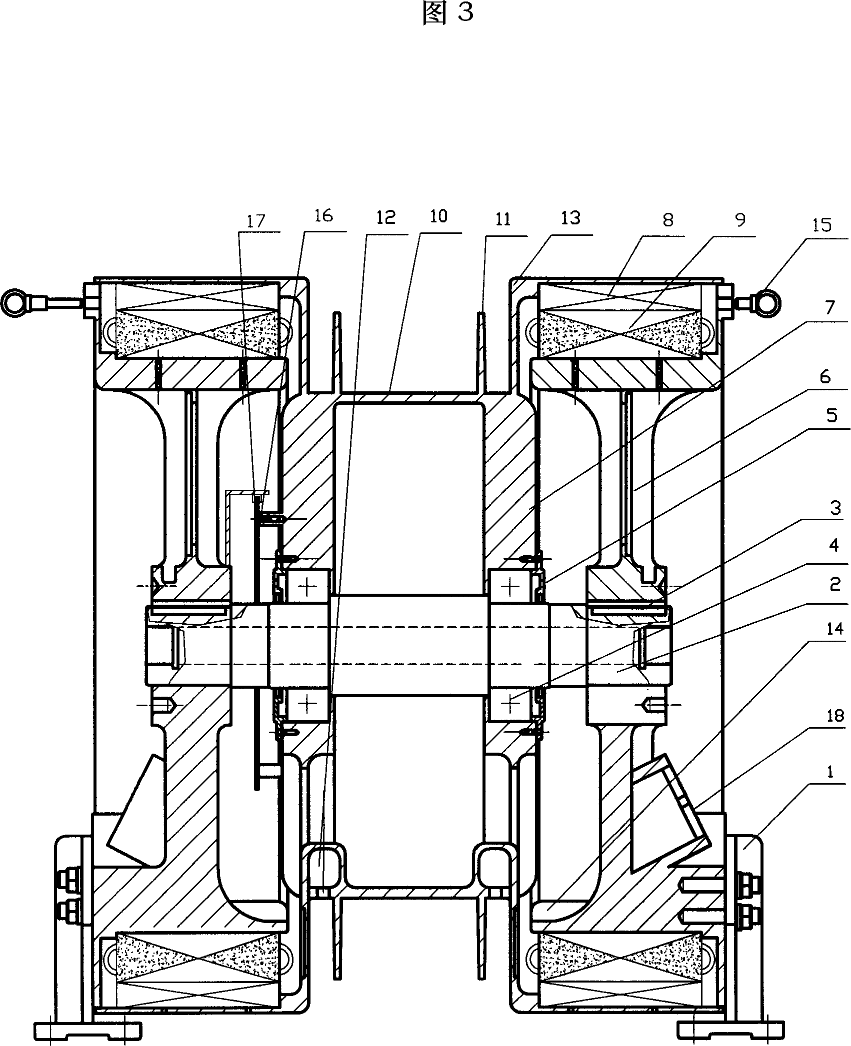
[0049] The special-shaped rotor ultra-low-speed high-torque short magnetic circuit speed-regulating motor of the present invention is also a drag device designed for mechanical oil production of oilfield tubular pumps. The prototype is an ultra-low-speed high-torque permanent-magnet speed-regulating motor with a special-shaped outer rotor structure. The special-shaped outer rotor and special-shaped inner stator shell are casted with cast steel at one time, and the outer rotor shell and the teeth are shielded with non-magnetic stainless steel. The maximum diameter of the outer rotor is ∮1412, the maximum outer diameter of the inner stator is ∮1210, and the main shaft is a hollow shaft. The rated speed of the prototype is 0-50 r / min, the rated torque is greater than 16kNm, and the maximum output power is 22kW, which is suitable for driving a Type 10 pumping unit.


PUM


Abstract

The invention belongs to the new area of electric magnetic application. The motor consists of the abnormal shape stator and rotator, the transducer/ controller and the magnetic short path system with large and small teeth. The stator and the rotator under the electrified phase possesses equal tooth space while under the non-electrified phase possesses unequal tooth space. Controlling timely the electrifying time of the electrified phase or the current magnitude produces the magnetic resistance rotary moment. Thus, the motor will rotate under the defined speed, rotary moment and various running states of direction changing, braking, and electrical motioning or generating. The motor possesses the advantages of simple structure, easy to control and saving consumption greatly. The invention suits to use in the oil-field tube-type pump mechanical oil drawing, the water wheel generator and other technique area with low speed and large rotary moment.

Description

Technical field: [0001] The invention is an ultra-low-speed, high-torque, short-magnetic-circuit speed-regulating motor with a special-shaped rotor, which is a major technological breakthrough for the mechanical oil production drag device of an oilfield tubular pump, and is the patentee's "Low-speed, high-torque special-shaped motor with high efficiency and low consumption". The core component of "Intelligent Pumping Unit" (ZL O2 2 57259.7), which belongs to the new field of electromagnetic application. Background technique: [0002] Since the electromagnetic theory was applied to motor practice in the 1840s, the development of electric drive devices has continued to introduce new ones in the past two hundred years, and various motors such as AC synchronous, AC asynchronous, DC shunt excitation, series excitation, and compound excitation have splendor. Diverse, single-phase, two-phase and three-phase. The application of motors has greatly improved productivity and product q...

Claims


Application Information

Patent Timeline
IPC IPC(8): H02K1/12H02K1/22H02K7/10H02K7/14H02K11/00H02K5/18H02K3/04H02K11/21
Inventor 王钢马强
Owner 王钢
Why Eureka
Try Eureka