Magnetic resonance steady state imaging

A magnetic resonance imaging and magnetic resonance image technology, which is applied in the direction of magnetic resonance measurement, measurement of magnetic variables, adjustment of magnetic variables, etc., can solve the problem of short magnetic resonance signal total scanning time and so on

Inactive Publication Date: 2007-05-16
KONINKLIJKE PHILIPS ELECTRONICS NV +1
View PDF0 Cites 2 Cited by
  • Summary
  • Abstract
  • Description
  • Claims
  • Application Information

AI Technical Summary

Problems solved by technology

[0003] In general, the steady-state MRI method has an extremely short total scan time for acquiring the MRI signal

Method used


Image

  • Magnetic resonance steady state imaging
  • Magnetic resonance steady state imaging

Examples


Embodiment Construction

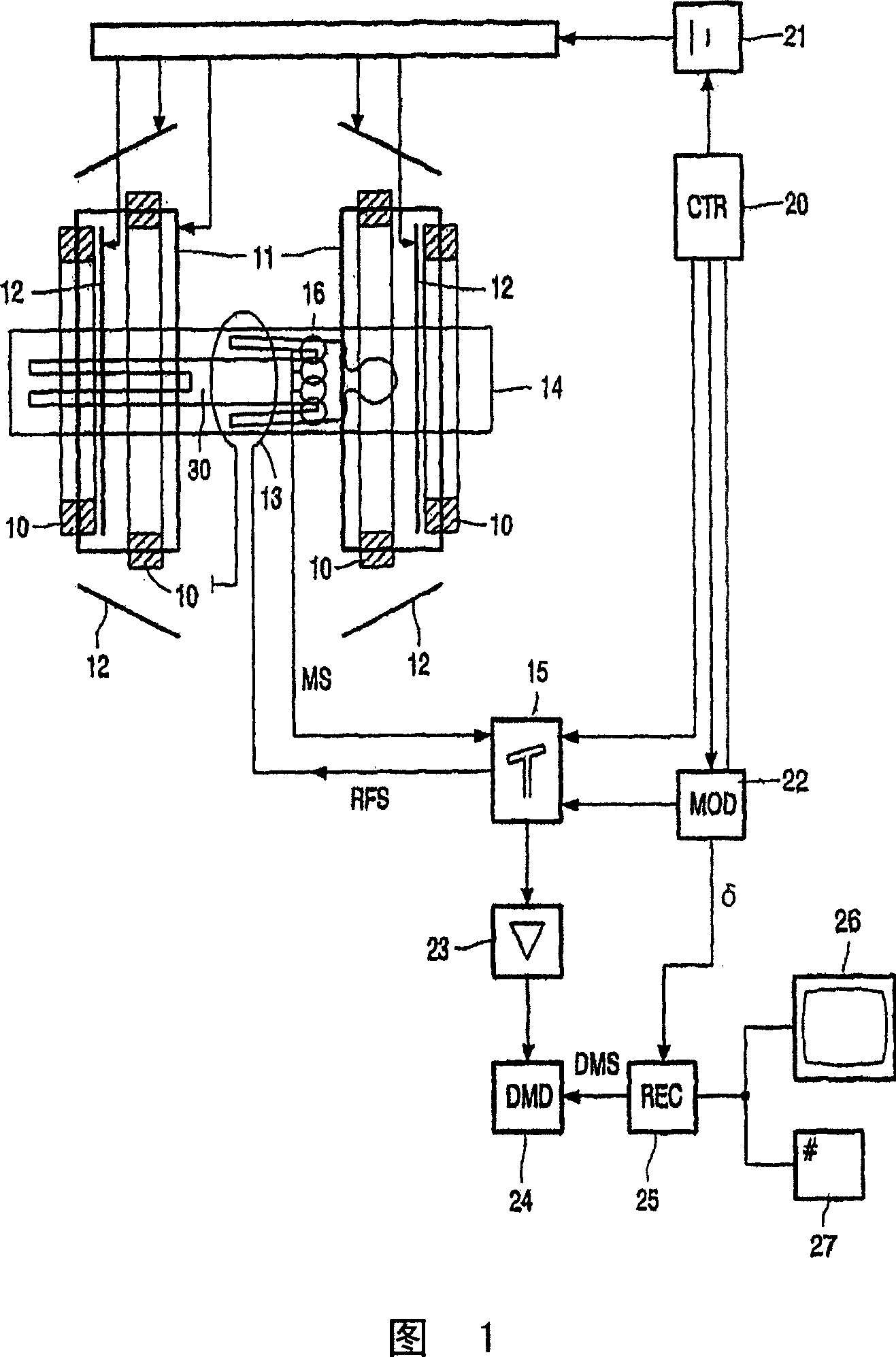
[0023] Figure 1 schematically represents a magnetic resonance imaging system in which the present invention is used. The magnetic resonance imaging system includes a set of main coils 10, thereby generating a stable and uniform magnetic field. The main coil is formed, for example, in such a way as to enclose a tunnel-shaped examination space. The patient to be examined is placed on a patient support which slides into this tunnel-shaped examination space. The magnetic resonance imaging system also includes a series of gradient coils 11, 12, whereby a magnetic field that exhibits a spatial variation is generated, in particular a magnetic field that varies in the form of instantaneous gradients in individual directions, so that this variable magnetic field can be superimposed on a uniform magnetic field . The gradient coils 11 , 12 are connected to a controllable power supply unit 21 . The gradient coils 11 , 12 can be excited by applying current through the power supply unit ...


PUM


Abstract

A high-sensitivity acquisition involves a (dynamic) steady-state that is achieved by repetitive applying flip angles with the same sign. Read-out of the magnetic resonance signals is done in the form of gradient echoes that are generated by applying temporary magnetic gradient fields. Preferably, all gradients are completely compensated for. Accordingly, a so-called Rephased Fast-Field Echo (R-FFE) sequence is employed as the high-sensitivity acquisition sequence. It appears that a high-sensitivity is achieved when a flip angle in the range from 3 DEG to 15 DEG is employed. High-sensitivity is achieved for very low concentrations of contrast agent in a range suitable for molecular imaging.

Description

technical field [0001] The invention relates to a magnetic resonance imaging system arranged to enable steady state magnetic resonance imaging. Background technique [0002] Steady-state magnetic resonance imaging is disclosed in the handbook "Magnetic Resonance Imaging" (2nd edition) by M.T. Vlaardingerbroek and J.A. den Boer (Springer Berlin 1999). [0003] In general, steady-state magnetic resonance imaging methods have extremely short overall scan times for acquiring magnetic resonance signals. Continuous RF excitation is achieved in the form of a series of consecutive RF excitation pulses so that the longitudinal and possibly transverse magnetization does not weaken back to zero. The magnetization preceding the RF excitation pulse is caused by many earlier RF excitation pulses. After a series of RF excitation pulses, a dynamic equilibrium is established in which both longitudinal and transverse magnetization components are present. In contrast-enhanced magnetic reson...

Claims


Application Information

Patent Timeline
IPC IPC(8): G01R33/561G01R33/28
CPCG01R33/5613G01R33/281
Inventor J·A·邓博尔R·M·J·N·拉默里奇斯K·尼科莱
Owner KONINKLIJKE PHILIPS ELECTRONICS NV
Why Eureka
Try Eureka