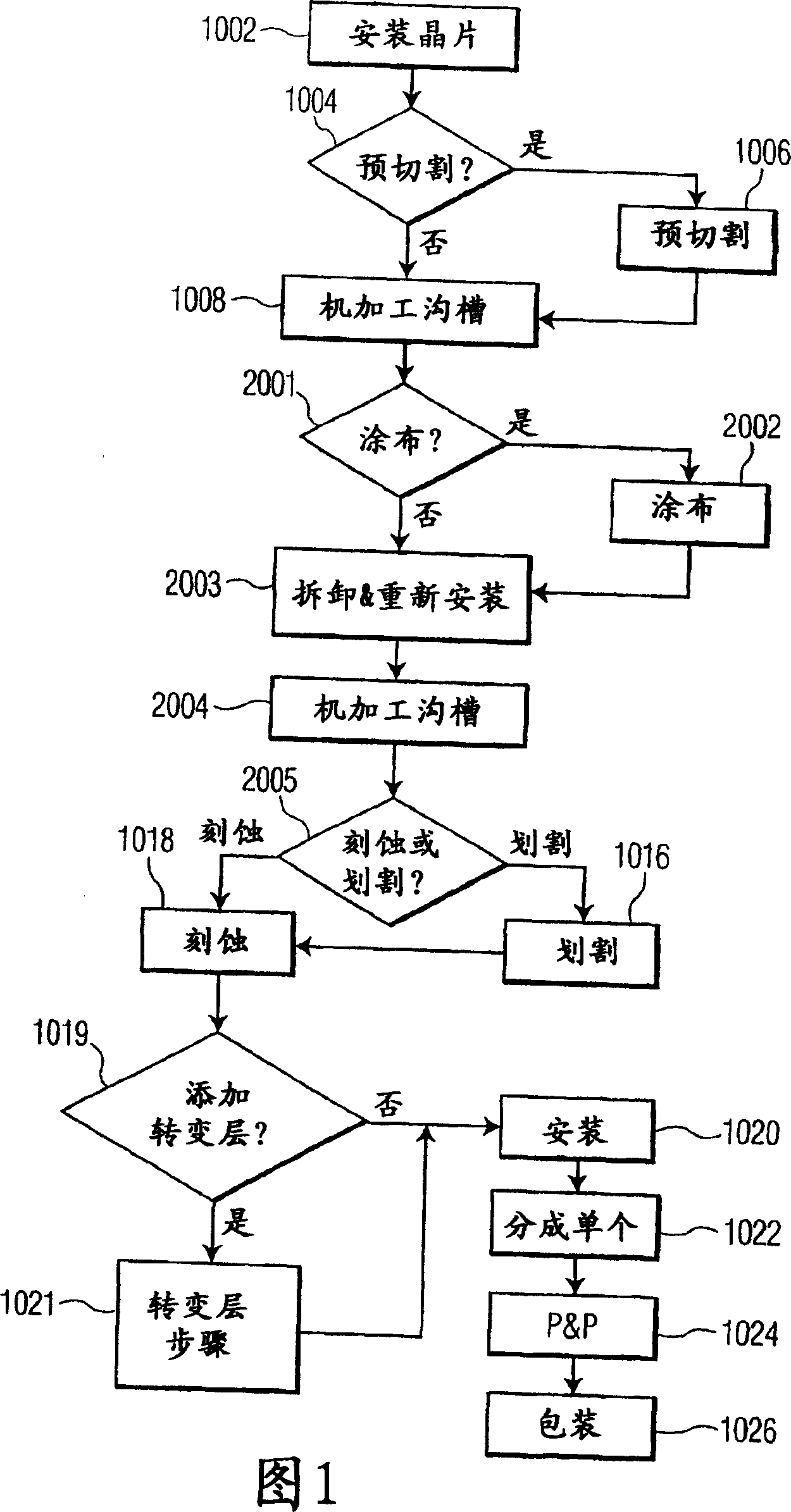
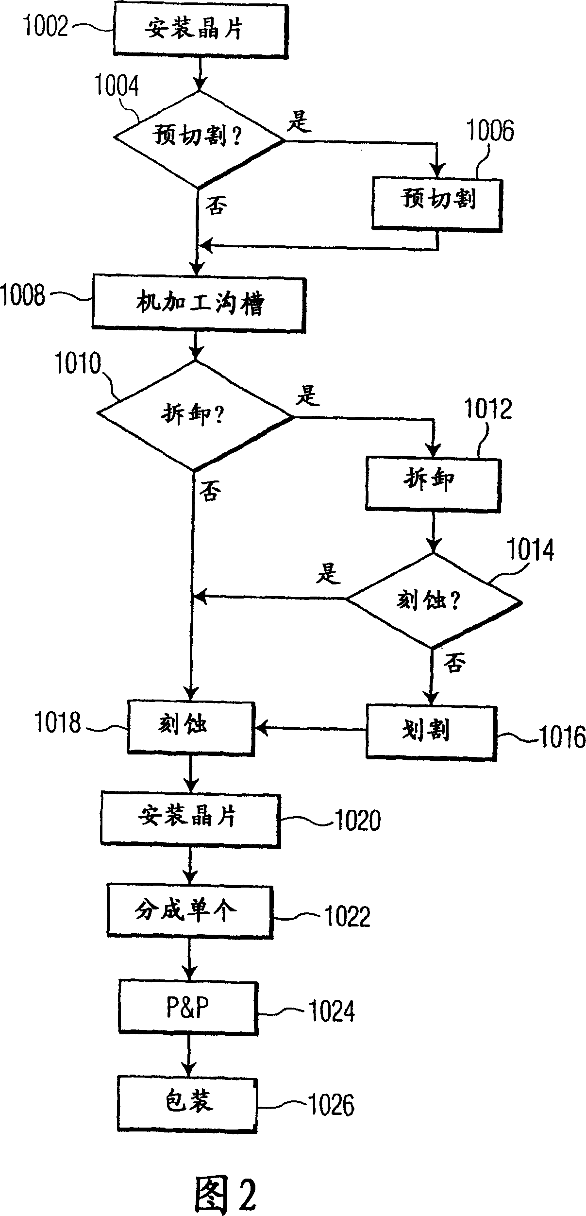
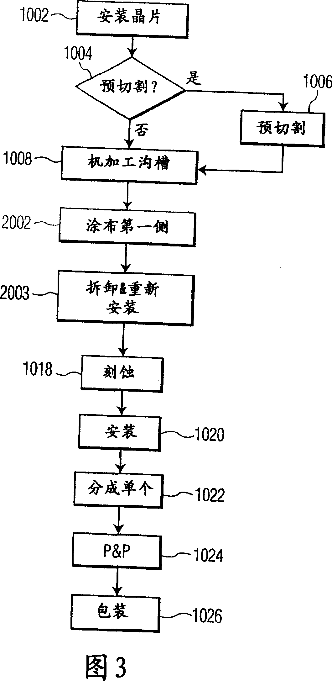
Methods of fabricating complex blade geometries from silicon wafers and strengthening blade geometries
A wafer manufacturing, blade technology, applied in the fields of ophthalmology, micro-surgical and non-surgical blades and mechanical devices, can solve the problems of bad cutting tools, low efficiency of ophthalmic blades, low efficiency, etc., and achieve the effect of cheap methods
- Summary
- Abstract
- Description
- Claims
- Application Information
AI Technical Summary
Problems solved by technology
Method used
Image

Examples
Embodiment Construction
[0069] Various features of the preferred embodiment will now be described with reference to the drawings, wherein like parts are designated by like reference numerals. The following description of what is presently believed to be the best mode of practicing the invention is not presented in a limiting sense, but merely to illustrate the general principles of the invention.
[0070] The systems and methods of the present invention provide a method of manufacturing a surgical blade for cutting soft tissue. Although the preferred embodiment is illustrated in terms of a surgical blade, a large number of cutting devices can also be fabricated according to the methods of the present invention discussed in detail below. Thus, it will be clear to those skilled in the art that although reference is made to "surgical blades" throughout these discussions, numerous other types of cutting devices can be manufactured including, for example, razors, lancets, hypodermic needles, sampling cann...
PUM
 Abstract
Description
Claims
Application Information