Lidar transmission-type confocal optical transceiver system

A laser radar and optical system technology, applied in optics, optical components, radio wave measurement systems, etc., can solve the difficulty of coaxial adjustment of the transmitting beam and receiving telescope system, the difficulty of adjusting the primary mirror and secondary mirror, and the loss of weak optical signals Intensity and other issues to achieve the effect of solving the beam matching problem, avoiding the drop in emissivity, and reducing the detection blind area

Inactive Publication Date: 2007-05-23
ANHUI INST OF OPTICS & FINE MECHANICS - CHINESE ACAD OF SCI
View PDF0 Cites 26 Cited by
  • Summary
  • Abstract
  • Description
  • Claims
  • Application Information

AI Technical Summary

Problems solved by technology

[0005] 1. The reflective telescope system is composed of a primary mirror and a secondary mirror. Each working mirror surface is coated with a metal film (such as aluminum film, gold film) or other dielectric film with a certain reflectivity. If the reflectivity of each mirror surface is 85%, the energy received by the telescope system is only 72.3% of the total energy, which greatly reduces the intensity of the received weak light signal
[0006] 2. In the reflective telescope system, the reflectivity of the aluminum coating or other dielectric film on the surface of the primary mirror and the secondary mirror will be greatly reduced during long-term work (especially field work)
For example, for a laser radar system that works outdoors for a long time, the aluminum coating on the mirror surface is prone to oxidation due to its poor corrosion resistance in harsh atmospheric environments.
[0007] 3. In the laser radar system, it is very difficult to install and adjust the main mirror and the auxiliary mirror by using the reflective telescope system, especially for the maintenance of the laser radar. If the main and auxiliary mirrors are changed, the optical path of the entire system must be re-adjusted make adjustments
[0008] 4. For the coaxial transceiver laser radar system, the laser beam is sent out through a mirror after passing through the beam expander collimation system. It is quite difficult to adjust the coaxiality of the emitting beam and the receiving telescope system. If there is a component position in the field test transportation Changes will cause the emitted beam to deviate from the optical axis of the receiving telescope system, which will seriously affect the performance of the entire radar system, or even fail to work properly
[0009] 5. For the off-axis transceiver laser radar system, it is necessary to ensure that the transmitting beam is parallel to the optical axis of the receiving telescope system in the entire radar system. This kind of working method is not only troublesome in adjustment, but also has a large gap in the detection space distance. Blind zone (at least greater than 400m), so overlap correction must be performed on the entire lidar system during work

Method used


Image

  • Lidar transmission-type confocal optical transceiver system
  • Lidar transmission-type confocal optical transceiver system

Examples


Embodiment Construction

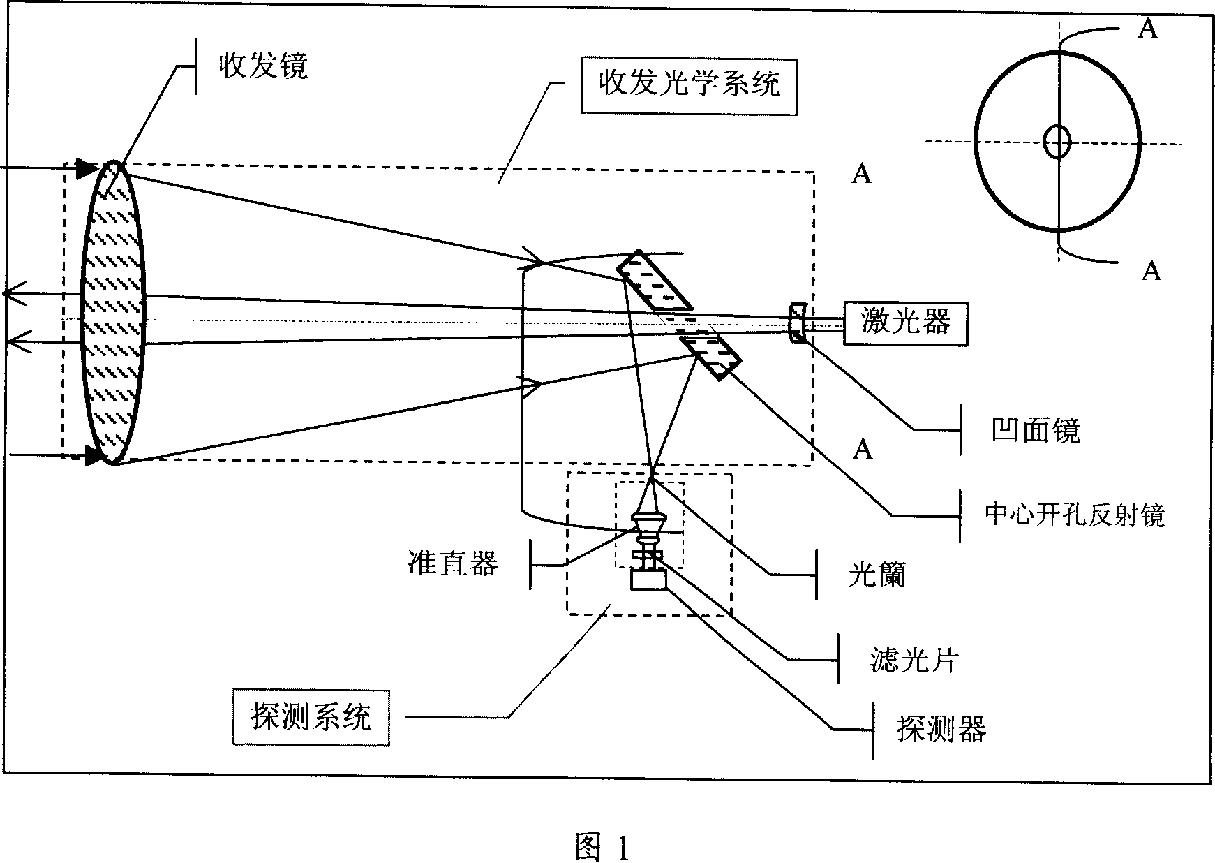
[0024] The laser radar transmissive confocal distance transmitting and receiving optical system is characterized in that it includes a transmitting optical unit composed of a concave mirror and a transmitting and receiving lens; a receiving optical unit composed of a transmitting and receiving lens and a central opening reflector. The transmitting optical unit and the receiving optical unit share a transceiver lens. A laser is installed on the wall of the lens barrel at the end of the lens barrel. The beam emitted by the laser passes through the concave mirror, the center hole of the central opening mirror, and the transceiver lens to emit parallel light. The central opening reflector is installed in the center of the lens barrel, and the center opening A transceiver lens is installed in front of the reflector, and the central opening reflector reflects the received beam to the detection system at 90 degrees. The concave mirror is located at the focal point of the transmissive ...


PUM


Abstract

This invention discloses a laser radar transmission total-focal length optical transceiver system. It is characterized by the optical emission module comprised by the concave mirror, and optical emission/receive lens, also by optical receive module comprised by optical emission/receive lens and mirrors with hole in the center. The central holed mirror is set up 45 degrees in the center of the tube. Receive and emitted mirrors are installed in front of the central holed mirror. The receive beam is redirected reflected of 90-degree beam to the detection systems.

Description

technical field [0001] The invention belongs to the transceiver optical system of laser radar. Background technique [0002] Lidar is one of the rapidly developing high-tech, and it is the product of the combination of traditional radar technology and modern laser technology. Lidar emits laser pulses into the air, and conducts atmospheric optical characteristics research by receiving the backscattering of laser pulses by aerosol particles in the atmosphere, and analyzes atmospheric visibility, aerosol particle spatiotemporal distribution and spatiotemporal changes, cloud base, cloud height, and boundary layer. Altitude, characteristics of aerosol particles, etc. Since the returned laser backscatter signal is very weak, in addition to using highly sensitive detectors for signal detection, the optical telescope that receives the laser backscatter signal is a key component that affects the performance of lidar. [0003] Whether it is a laser radar with a coaxial transmitting ...

Claims


Application Information

Patent Timeline
Patent Type & Authority Applications(China)
IPC IPC(8): G01S7/481G02B27/00
Inventor 刘文清赵南京张玉钧刘建国刘诚张天舒司福祺陆亦怀谢品华魏庆农
Owner ANHUI INST OF OPTICS & FINE MECHANICS - CHINESE ACAD OF SCI
Why Eureka
Try Eureka