Micro robot and its in vitro guiding system

A micro-robot, guidance system technology, applied in surgical robots, pipeline systems, sensors, etc., can solve problems such as poor attitude control and movement flexibility

Inactive Publication Date: 2007-06-06
INST OF ELECTRICAL ENG CHINESE ACAD OF SCI
View PDF7 Cites 36 Cited by
  • Summary
  • Abstract
  • Description
  • Claims
  • Application Information

AI Technical Summary

Problems solved by technology

[0008] The purpose of the present invention is to overcome the disadvantages of poor attitude control and movement flexibility in the existing micro-robot drive technology, learn from the movement mode of magnetotactic bacteria, and propose a bionic micro-robot with active helical propulsion combined with external magnetic field attitude control. in vitro guidance system

Method used


Image

  • Micro robot and its in vitro guiding system
  • Micro robot and its in vitro guiding system
  • Micro robot and its in vitro guiding system

Examples


Embodiment Construction

[0051] The present invention will be further described below in conjunction with the accompanying drawings and specific embodiments.

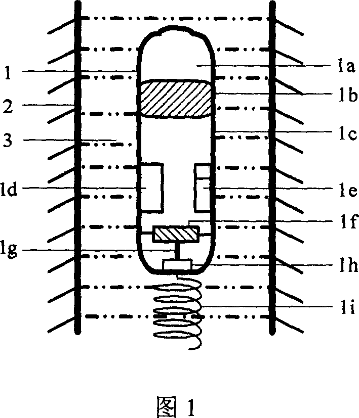
[0052]The internal structure of the micro-robot 1 is shown in Figure 1. Its front end is smooth, and its outer wall has no protrusions or grooves. There is a spiral groove on the outer peripheral surface of the permanent magnet block 1b, which is airtightly matched with the spiral groove at the inner front end of the fuselage 1a. The tail rotating mechanism 1h is fixedly connected with the tail 1i through a rotating rod protruding from the inside of the fuselage. The tail rotating mechanism 1h is composed of a worm 1g, a worm gear, a cam, a rotating rod, a bottom plate, a hinge, a permanent magnet and an electromagnetic coil. The worm 1g is installed on the main shaft of the micromotor 1f. The worm wheel and the cam are coaxially arranged, and the rotating shaft of the worm wheel is installed on the bottom plate. , the bottom plate is pasted o...


PUM


Abstract

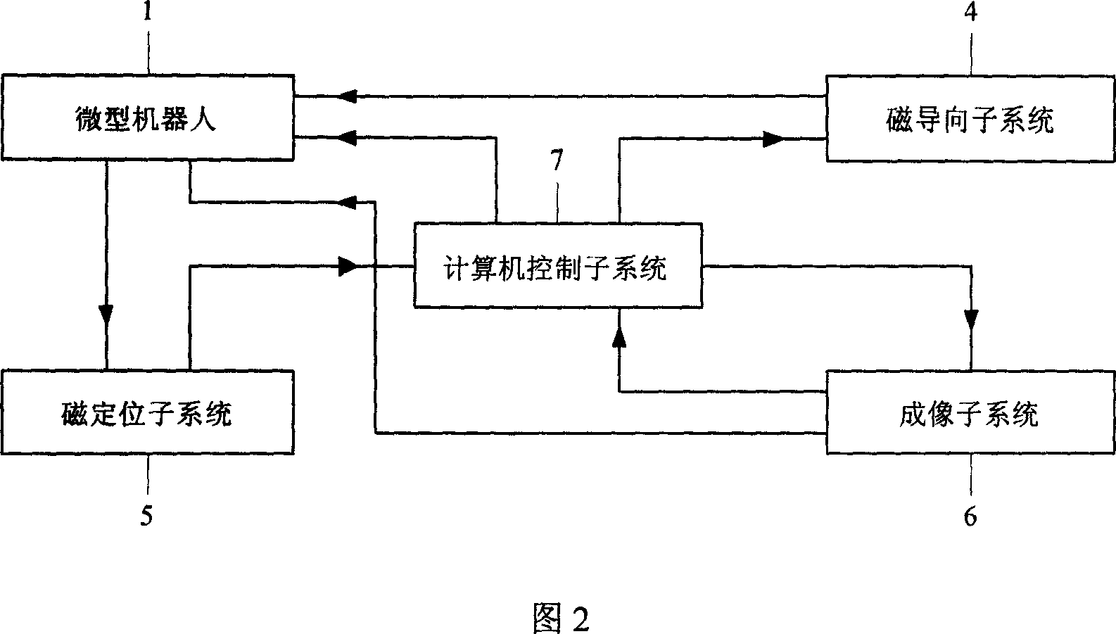
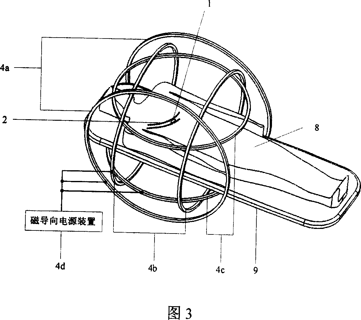
The present invention is one kind of micro robot and its in vitro guiding system. Inside the robot, there are permanent magnet, micromotor, RF receiver, miniature battery, tail rotating mechanism, tail rotating rod and high elasticity sealing membrane between the rotating rod and the robot body. The in vitro guiding and controlling system includes an imaging subsystem for scanning the detected area, a computerized control subsystem for receiving the original image data and performing image reconstitution, a magnetically locating subsystem for locating the permanent magnet inside the robot and feeding the original location data to the computerized control subsystem, and a magnetically guiding subsystem for receiving the guide controlling information from the computerized control subsystem and performing the guide control on the micro robot.

Description

technical field [0001] The invention relates to the technical field of bionic micro-robots, in particular to a micro-robot and an in vitro guidance system thereof. Background technique [0002] With the development of robot technology and micro-electro-mechanical systems, micro-robots have become a research hotspot at home and abroad, especially the development and application of wireless endoscopes that enter the human body, vascular robots, and micro-robots for the detection of small pipelines in industrial equipment. are especially valued. Due to the special working environment, this type of micro-robot cannot be a simple miniaturization of ordinary robots, especially in the way of driving will be very different from ordinary robots. At present, the driving methods of micro-robots can be roughly divided into two categories: one is driven by the actuator of the robot body; The actuator realizes wireless drive through external field excitation. [0003] For the driving m...

Claims


Application Information

Patent Timeline
Patent Type & Authority Applications(China)
IPC IPC(8): A61B1/00A61B17/00A61B5/00A61B19/00F17D5/00A61B34/30
CPCA61B34/73A61B1/00158A61B1/041
Inventor 宋涛李晓南王铮王明
Owner INST OF ELECTRICAL ENG CHINESE ACAD OF SCI
Why Eureka
Try Eureka