Upstream chain receiving method and apparatus in distribution antenna mobile communication system

A technology of a mobile communication system and a receiving method, which is applied in the field of uplink receiving of distributed antenna mobile communication, can solve problems such as the limit of the number of processing capacity used, the limit of system performance improvement, and the large system path loss, so as to improve beamforming efficiency, Reduce system complexity and save equipment cost

Inactive Publication Date: 2007-06-13
SOUTHEAST UNIV +1
View PDF0 Cites 20 Cited by
  • Summary
  • Abstract
  • Description
  • Claims
  • Application Information

AI Technical Summary

Problems solved by technology

Second, the resource limitation of mobile communication spectrum in the future makes the communication system work in a higher frequency band, and the path loss of the system is relatively large, especially when the carrier frequency of the signal is greater than 3GHz, which is not conducive to the design of mobile communication systems including MIMO systems ; Third, there is shadow fading in the mobile communication system. When the mobile terminal is in the deep shadow fading area, the signal-to-noise ratio of the MIMO system is low, and the bit error rate of the signal will be greatly increased.
[0004] In a generalized distributed antenna system, referring to Figure 1, each distributed radio access unit (RAU) has multiple antenna arrays composed of antenna units, and the received signals of all antenna arrays at multiple distributed radio access units It is transmitted to the transceiver base station through optical fiber or coaxial cable for centralized processing, where MT stands for mobile station, but due to the large number of antennas, the amount of data processed by the base station is very large, which affects the feasibility of the hardware design of the base station equipment, and the number of antennas used is due to the equipment The processing power of the system is also limited, which leads to the limitation of system performance improvement

Method used


Image

  • Upstream chain receiving method and apparatus in distribution antenna mobile communication system
  • Upstream chain receiving method and apparatus in distribution antenna mobile communication system
  • Upstream chain receiving method and apparatus in distribution antenna mobile communication system

Examples


Embodiment Construction

[0034] The present invention will be further described below in conjunction with the accompanying drawings.

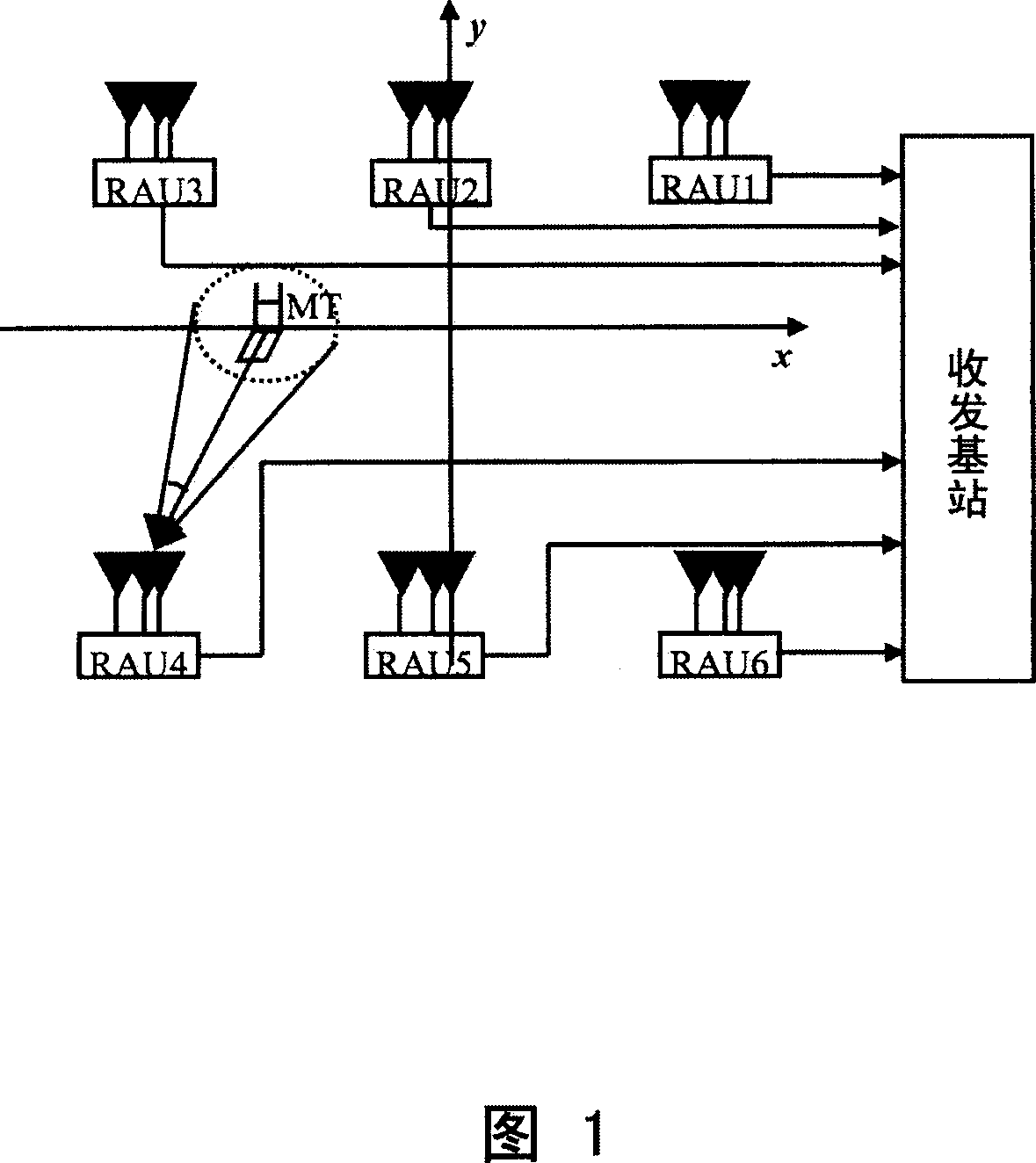
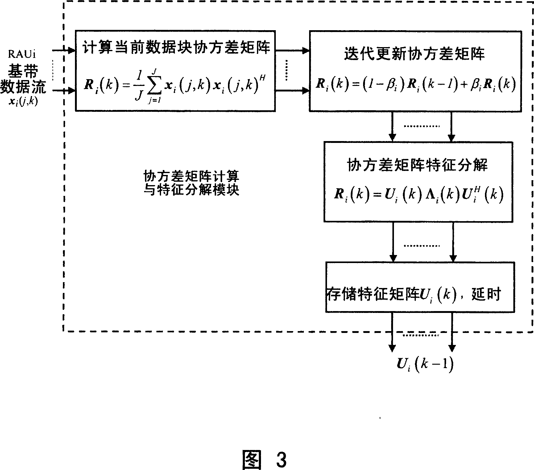
[0035] Figure 3 vividly shows the process of calculating the covariance matrix and the eigendecomposition of the matrix by the iterative method with the implementation block diagram and mathematical formulas. In this embodiment, there are two RAUs (RAU1 and RAU2), and each RAU has an example of three antennas or antenna sub-arrays. The mobile station has two transmit antennas, and each antenna transmits different data. Then, there are 100 samples in time to transmit a data block, and each sample is composed of two different signal space multiplexing. The length of the training sequence has 2 samples, corresponding to sample 1 and sample 2. The remaining 98 samples transmit unknown information data, corresponding to samples 3 to 100. Of course, the present invention is not limited to the above-mentioned mobile stations, and any data sent by any kind of mobile station...


PUM


Abstract

The device includes at least two distributed type wireless access unit, at least two antennae contained in each wireless access unit. The device also includes following modules: covariance matrix calculation and character decomposion module is in use for calculating covariance matrix of baseband data corresponding to each distributed type wireless access unit, and carrying out character decomposion for the covariance matrix so as to obtain eigen vector matrix; projection value calculation module is in use for calculating projection value by using the covariance matrix and the eigen vector matrix; module for selecting eigen vector is in use for selecting eigen vector corresponding to large projection value of specific number; synthetical signal forming module is in use for carrying out weighting calculation for baseband data by using eigen vector as weighted vector so as to form a route of synthesized signal.

Description

technical field [0001] The invention relates to a method for receiving an uplink of a distributed antenna mobile communication, and relates to a method for receiving an uplink of a mobile communication in a generalized distributed antenna system (GDAS). Background technique [0002] With the development of communication technology and people's requirements for high-speed data communication, a technology based on MIMO (Multiple Input Multiple Output) has been applied. In MIMO, multiple different data streams are transmitted from different antennas, and multiple antennas at the receiving end receive and demodulate the data. This multiplexing-based spatial multiple access method can double the spectrum efficiency. However, there are three key factors that limit the improvement of MIMO performance. First, signals received in uplink in normal mobile communications have spatial correlation. Second, the resource limitation of mobile communication spectrum in the future makes the ...

Claims


Application Information

Patent Timeline
IPC IPC(8): H04B7/08H04J99/00
Inventor 王炎尤肖虎张战加山英俊潘振岗陈岚
Owner SOUTHEAST UNIV
Why Eureka
Try Eureka