Waste heat recovery apparatus, waste heat recovery system, and method of recovering waste heat

A technology of waste heat recovery and sensible heat recovery, applied in charging systems, gas turbine devices, chemical instruments and methods, etc., can solve the problems of not being able to become and not getting fuel

Inactive Publication Date: 2007-06-13
JFE技研株式会社
View PDF1 Cites 6 Cited by
  • Summary
  • Abstract
  • Description
  • Claims
  • Application Information

AI Technical Summary

Problems solved by technology

But in this method, H cannot be obtained without a coke oven 2 fuel, so it cannot be widely used in the future as a fuel for fuel cells, etc. 2 source of fuel

Method used


Image

  • Waste heat recovery apparatus, waste heat recovery system, and method of recovering waste heat
  • Waste heat recovery apparatus, waste heat recovery system, and method of recovering waste heat
  • Waste heat recovery apparatus, waste heat recovery system, and method of recovering waste heat

Examples


Embodiment Construction

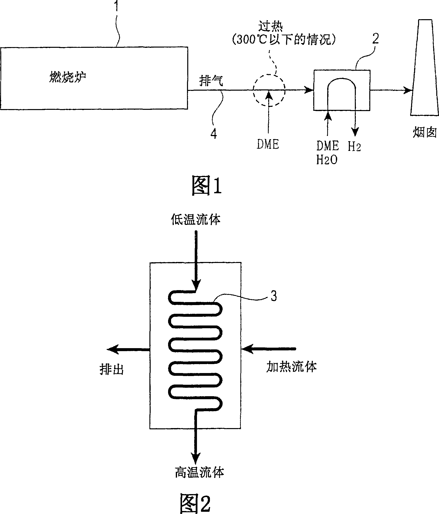
[0055] Embodiments of the present invention will be described below. FIG. 1 shows a waste heat recovery device according to a first embodiment of the present invention. A heat exchanger 2 is provided on the exhaust system 4 of the combustion furnace 1, and dimethyl ether (hereinafter referred to as DME) and water vapor (hereinafter referred to as H 2 O) The mixed gas passes through the heat exchanger 2. Through the heat exchange between the exhaust gas and DME in the heat exchanger 2, the DME is thermally decomposed into H 2 , recovering the sensible heat of the exhaust gas as H 2 fuel.

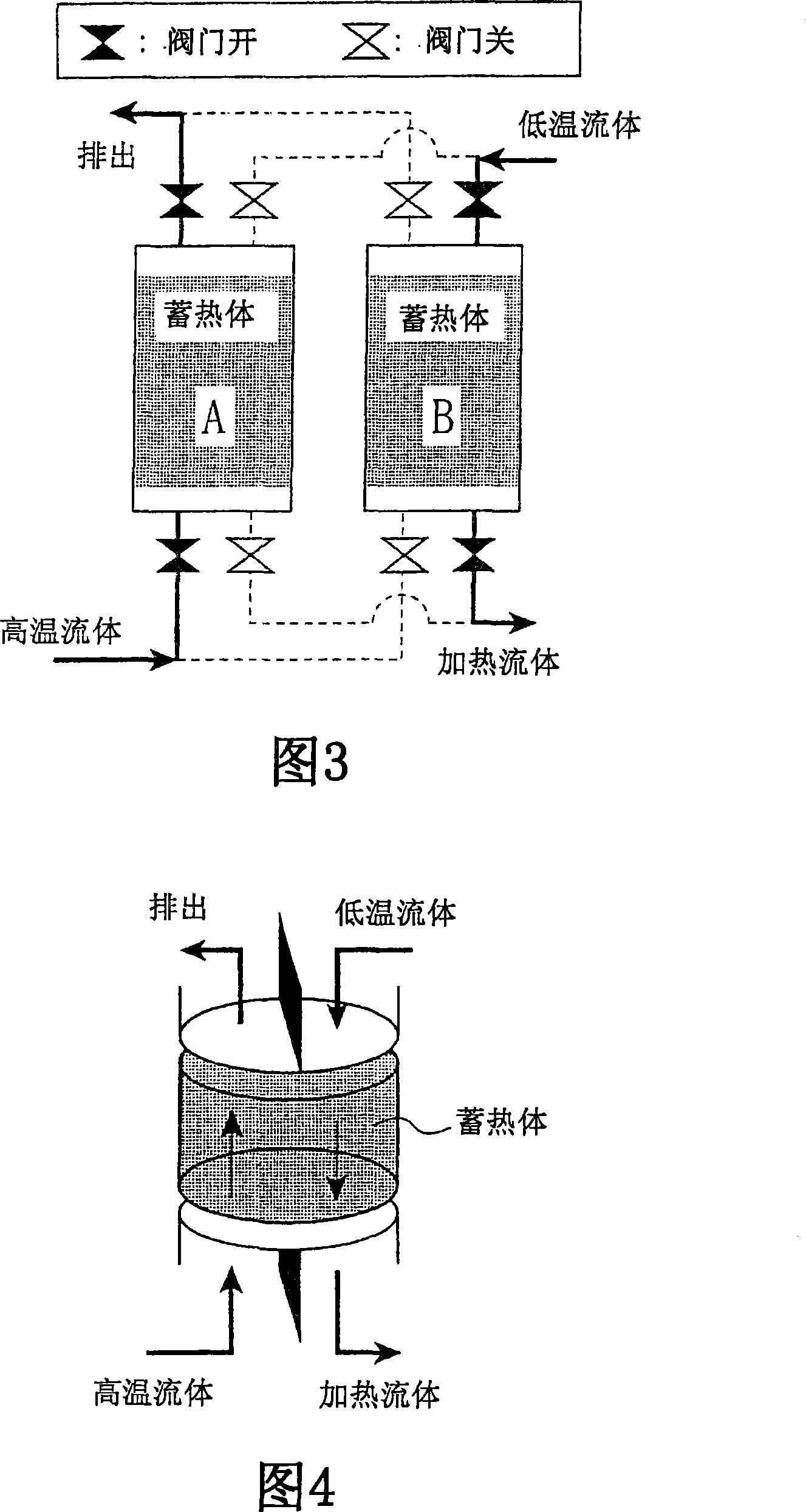
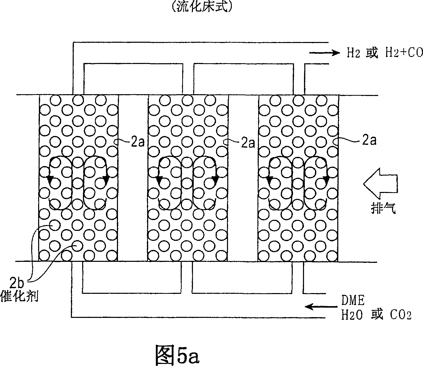
[0056] As the heat exchanger 2, various structures such as a tube type, a plate type, an enlarged heat transfer surface, a heat storage type, a fluidized bed type, and a heat medium circulation type can be used. Figure 2 shows an example of a tubular heat exchanger (recovery heat exchanger called a recuperator), Figures 3 and 4 show a heat storage heat exchanger, and Figure 5 shows a flui...


PUM


Abstract

A heat exchanger packed with a catalyst for reforming DME is installed in the discharge line of a combustion apparatus such as a furnace, an internal combustion engine or electric power generation facilities. A mixed gas from DME and H2O is passed through the heat exchanger, to thereby pyrolyze DME and recover the sensible heat of the exhaust gas from a furnace or an internal combustion engine as an H2 fuel. Since waste heat is recovered as an H2 fuel or an H2 and CO fuel, not simply as steam, warm water, hot air or the like, the energy recovered by the above method is not limited in the use thereof.

Description

technical field [0001] The present invention relates to a method for recovering waste heat discharged from various industrial sectors, in particular to a waste heat recovery device and method for recovering waste heat of exhaust gas discharged from combustion devices such as furnaces, internal combustion engines or power generation equipment. Background technique [0002] People have been devoting themselves to recovering the waste heat of the exhaust gas emitted by combustion devices such as various furnaces represented by fuel-burning furnaces, internal combustion engines or power generation equipment, so as to achieve the actual effect of energy saving. [0003] As a method of recovering waste heat of exhaust gas, a method of recovering sensible heat of exhaust gas as thermal energy is generally implemented. Specifically, a heat exchanger is provided on the exhaust system of the combustion device, and the heat recovery medium is passed through the heat exchanger, and the ...

Claims


Application Information

Patent Timeline
IPC IPC(8): F02C7/22F02C3/22F02C6/18F02G5/02H01M8/06C01B3/22
CPCY02T10/32Y02T10/126Y02T10/166F28D21/001Y02E60/50Y02T10/16Y02P20/10Y02P20/129Y02T10/12
Inventor 中川二彦林宏优
Owner JFE技研株式会社
Why Eureka
Try Eureka