Magnet roller

A technology of magnetic rollers and magnetic blocks, applied in the directions of magnets, magnetic objects, magnetic materials, etc., can solve the problems of high cost, difficulty in forming magnetic flux density patterns, etc. Effect

Inactive Publication Date: 2007-06-13
KANEKA CORP +1
View PDF2 Cites 0 Cited by
  • Summary
  • Abstract
  • Description
  • Claims
  • Application Information

AI Technical Summary

Problems solved by technology

That is, the orientation direction of the magnetic particles of the magnetic block is parallel to the radial centerline or perpendicular to the radial centerline (that is, if viewed from the joint surfaces of adjacent magnetic blocks, the vertical direction of the magnetic particles relative to the joint surface Parallel orientation) orientation, since the orientation of the magnetic particles is not inclined with respect to the parallel line or the vertical line, although it is not shown in Patent Document 1, only a simple magnetic flux density pattern is formed
In addition, in this patent, eight magnetic blocks are used in order to obtain four magnetic poles, so there is a problem of high cost
[0008] In addition, as shown in Patent Document 2, after injection-molding a magnetic block whose cross-sectional shape is fan-shaped and the easy magnetization axis of ferrite powder is oriented from the center of the arc to the other three sides to magnetize it, multiple Bonded to the main shaft to form a magnetic block, so although it is not shown in Patent Document 2, it is difficult to form a complex magnetic flux density pattern after all, so there is a problem that only a simple magnetic flux density pattern can be formed

Method used


Image

  • Magnet roller
  • Magnet roller
  • Magnet roller

Examples


Embodiment 1

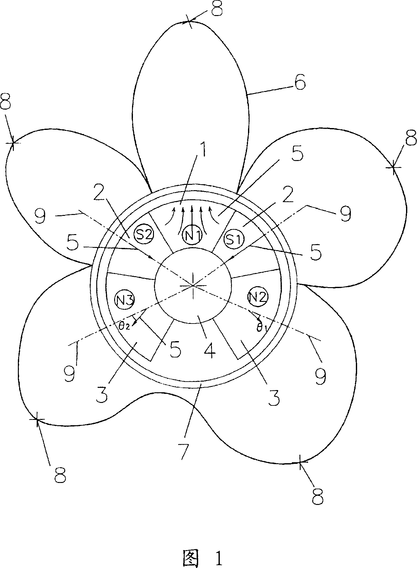
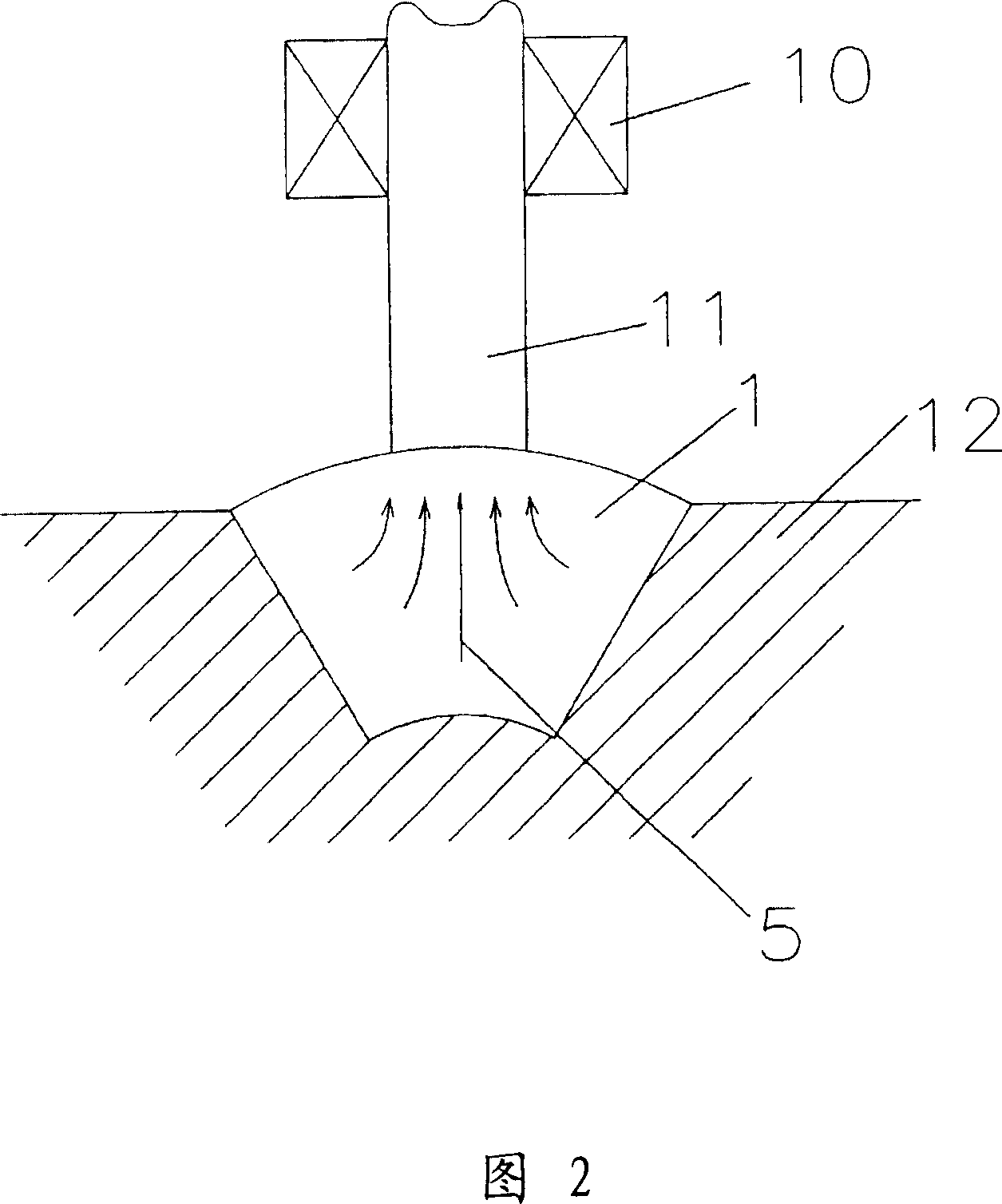
[0075] As the magnetic block material for the N1 pole in Fig. 1, 10% by weight (including lubricant, plasticizer, and stabilizer) of nylon 6 (Ube Industries, Ltd. P1010) was used as the resin binder, and 90% by weight was used as the magnetic powder. % anisotropic strontium ferrite magnetic powder (SrO·6Fe 2 o 3 ), mix them and melt and stir them to form granules, and make the granules into a molten state, use the mold shown in Figure 2 to inject the molten resin magnet material from the injection port, and apply a magnetic field of 1200K·A / m to make the molten resin magnet The polarity of the magnetic particles is anisotropically oriented and magnetized, and the N1 pole of the magnetic block shown in FIG. 1 is injection molded.

[0076] In addition, as a magnetic block material for poles other than the N1 pole (S1 pole, N2 pole, N3 pole, S2 pole) in Figure 1, the resin binder uses 10% by weight (including lubricants, plasticizers, stabilizers) chlorine Polyethylene (Ebaslen...

Embodiment 2

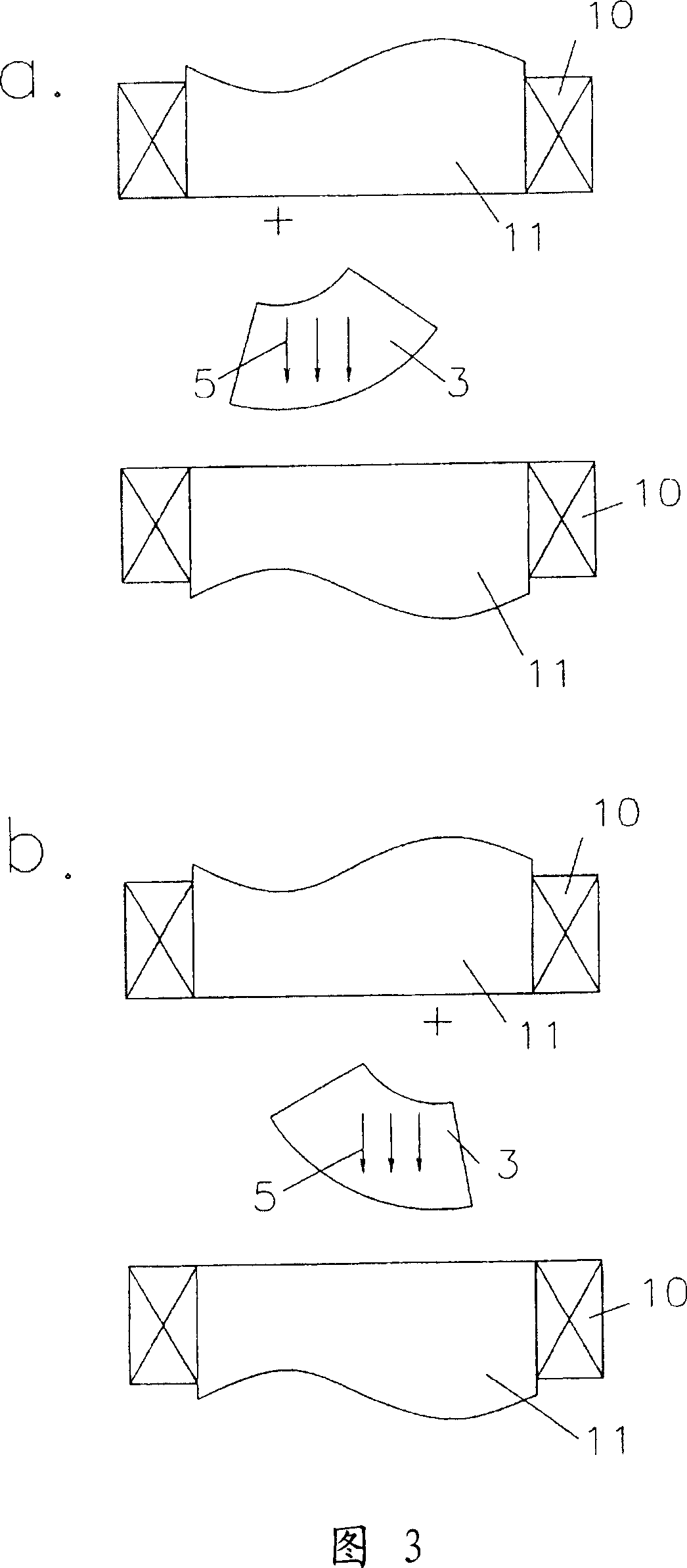
[0084]As the magnet material for extrusion molding (S1 pole, N2 pole, N3 pole, S2 pole), the resin binder adopts 10% by weight (including lubricant, plasticizer, stabilizer) of ethylene ethyl acrylate (Japanese Yuerka No.1 PES-210), as the magnetic powder adopts 90% by weight anisotropic strontium ferrite magnetic powder (SrO·6Fe 2 o 3 ), they are mixed and melted and stirred to form granules, and the granules are in a molten state, using the dies (extrusion dies) of a, b in Figure 3 and a, b in Figure 4, while applying 240K·A / m~ A magnetic field of 2400K·A / m was used to orient and magnetize the magnetic particles of the molten resin magnet in one direction for each piece, and extrusion molding was carried out. The same procedure as in Example 1 was carried out.

[0085] Tables 1 to 4 show the measurement results.

Embodiment 3

[0087] As the magnet material for injection molding (N1 pole), nylon 12 (Ube Industries Co., Ltd. P3012U) with 10% by weight (including lubricant, plasticizer, and stabilizer) is used as the resin binder, and 90% by weight is used as the magnetic powder. % anisotropic strontium ferrite magnetic powder (SrO·6Fe 2 o 3 ), except that, the same steps as in Example 1 were carried out.

[0088] Tables 1 to 4 show the measurement results.


PUM


Abstract

In a magnet roller of the magnet piece bonding type, the main pole has a high magnetic flux density and the other pole has an asymmetric magnetic flux density pattern with respect to the magnetic flux density peak position. The magnet piece of the main pole is formed by injection molding while performing pole-anisotropic orientation of magnetic particles of the magnet piece. The magnet piece of the other pole is formed by extrusion molding while orientating the magnetic particles in a certain direction inclined by 5 degrees or more with respect to the center line of the radial direction of the magnet piece. The magnet roller is formed by combining the magnet piece of the main pole and the magnet piece of the other pole.

Description

technical field [0001] The present invention relates to a magnet roller incorporated in, for example, an image forming apparatus such as a copying machine, a printer, a facsimile machine, or the like. Background technique [0002] A magnet roller of an image forming apparatus using powder toner, which is generally incorporated in a copying machine, a printer, a facsimile machine, etc., is configured as follows. [0003] That is, (1) A magnet roll is formed by fixing a plurality of magnet blocks having their magnetization-easy axes oriented in a specific direction simultaneously with extrusion molding on a spindle (Patent Document 1). [0004] (2) After injection-molding a magnetic block whose cross-sectional shape is fan-shaped and magnetized by orienting the easy-magnetization axis of the ferrite powder from the center of the arc to the other three sides, a plurality of them are bonded to the main shaft to form a magnet. A magnetic block is formed (Patent Document 2). [...

Claims


Application Information

Patent Timeline
Patent Type & Authority Applications(China)
IPC IPC(8): G03G15/09H01F7/02H01F41/02
CPCH01F41/028H01F1/113H01F41/0266G03G15/0921H01F7/0268
Inventor 岩井雅治
Owner KANEKA CORP
Why Eureka
Try Eureka