Target and process kit components for sputtering chamber

A sputtering target and sputtering chamber technology, applied in metal material coating process, sputtering plating, electrical components, etc., can solve the problems of increased process cost, thermal stress peeling, contamination of the substrate, etc., and can prolong the start-up time. effect of time, uniform deposition, increased throughput

Active Publication Date: 2007-06-20
APPLIED MATERIALS INC
View PDF0 Cites 8 Cited by
  • Summary
  • Abstract
  • Description
  • Claims
  • Application Information

AI Technical Summary

Problems solved by technology

However, sputtered deposits that build up on process kit components can also be peeled off during the cleaning cycle by the thermal stresses generated in the process cycle
Deposits that flake off inside the chamber can contaminate the substrate and are also undesirable
While chambers can be shut down for short intervals to clean kit components, the resulting chamber downtime further increases process cost

Method used


Image

  • Target and process kit components for sputtering chamber
  • Target and process kit components for sputtering chamber
  • Target and process kit components for sputtering chamber

Examples


Embodiment Construction

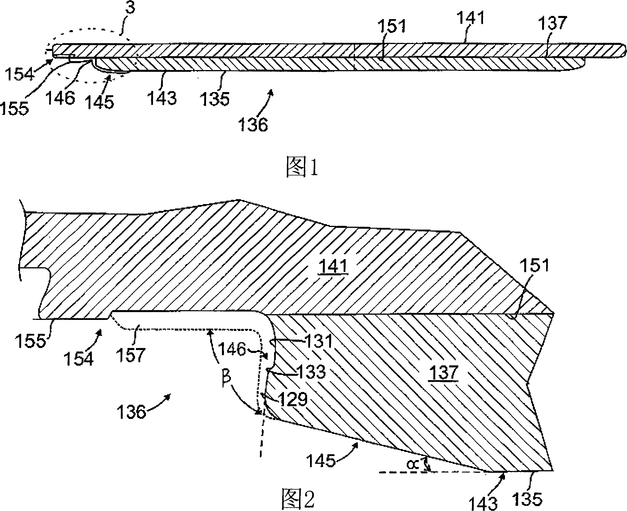
[0038] 1 and 2 illustrate an exemplary embodiment of a sputter target 136 that may be used in a sputter processing chamber to deposit sputtered material on a substrate. As shown in the exemplary chamber embodiment of FIG. 9 , during processing in chamber 100 , sputtering surface 135 of sputtering plate 137 of target 136 is positioned opposite substrate 104 . In one aspect, the sputtering plate 137 includes a central cylindrical mesa 143 with a sputtering surface 135 forming a plane parallel to the plane of the substrate 104 . The annular sloped side 145 surrounds the columnar mesa 143 . In one aspect, the annular edge 145 is inclined at an angle α of at least about 8°, eg, from about 10° to about 20°, eg, 15°, relative to the plane of the cylindrical mesa 143 . A peripheral sloping side wall 146 with a step 133 surrounds the annular edge 145 . The peripheral sloped sidewall 146 is sloped at an angle β of at least about 60° relative to the plane of the cylindrical mesa 143 , ...


PUM

PropertyMeasurementUnit
surface roughnessaaaaaaaaaa
mean roughnessaaaaaaaaaa

Abstract

A process kit for a sputtering chamber comprises a deposition ring, cover ring, and a shield assembly, for placement about a substrate support in a sputtering chamber. The deposition ring comprising an annular band with an inner lip extending transversely, a raised ridge substantially parallel to the substrate support, an inner open channel, and a ledge radially outward of the raised ridge. A cover ring at least partially covers the deposition ring, the cover ring comprising an annular plate comprising a footing which rests on a surface about the substrate support, and downwardly extending first and second cylindrical walls.

Description

[0001] Cross References to Related Applications [0002] This application is entitled under 35USC119(e) to (i) a provisional application filed on November 25, 2005 entitled "TARGET AND PROCESS KIT FORTITANIUM SPUTTERING CHAMBER" Priority of No. 60 / 739,658 and (ii) provisional application filed March 30, 2006 entitled "TARGET AND PROCESS KIT COMPONENTS FOR SPUTTERING CHAMBER" Priority of No. 60 / 788,378. Both provisional applications are hereby incorporated by reference in their entirety. technical field [0003] The present invention relates to targets for sputtering chambers. Background technique [0004] In the manufacture of integrated circuits and displays, substrates such as semiconductor wafers and display panels are placed in processing chambers and process conditions in the chamber are set to deposit materials on or etch the substrates. A typical chamber includes a peripheral wall surrounding the plasma region, a substrate holder for supporting the substrate, a gas...

Claims


Application Information

Patent Timeline
Patent Type & Authority Applications(China)
IPC IPC(8): C23C14/35C23C14/14C23C14/46
CPCH01J37/3435H01J37/34H01J37/32477C23C14/34H01J37/3423C23C14/46C23C14/3407H01J37/3408C23C14/35H01J37/3426C23C14/14H01J37/3497
Inventor 艾伦·亚历山大·里奇唐尼·扬扬·理查德·洪凯瑟琳·A·沙伊贝尔乌梅什·凯尔卡
Owner APPLIED MATERIALS INC
Why Eureka
Try Eureka