Ultrasonic inspection of petroleum pipeline and inspecting robot

A technology of oil pipelines and detection methods, which is applied in the field of robots, can solve the problems of low energy consumption, and achieve the effects of low energy consumption, simple structure, and improved efficiency

Inactive Publication Date: 2007-06-20
BEIHANG UNIV
View PDF0 Cites 38 Cited by
  • Summary
  • Abstract
  • Description
  • Claims
  • Application Information

AI Technical Summary

Problems solved by technology

The robot can record the detection results into the memory through the single-chip microcomputer, and the ener

Method used


Image

  • Ultrasonic inspection of petroleum pipeline and inspecting robot
  • Ultrasonic inspection of petroleum pipeline and inspecting robot
  • Ultrasonic inspection of petroleum pipeline and inspecting robot

Examples


Embodiment Construction

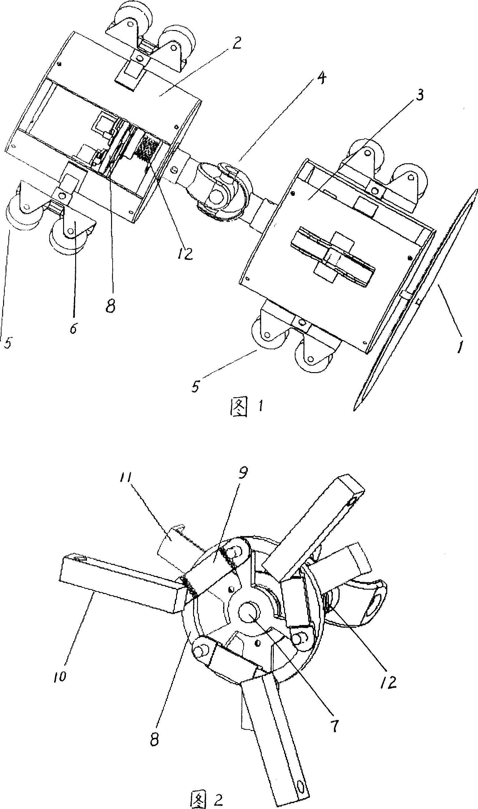
[0021] As shown in Figures 1 and 2, the present invention provides a method for ultrasonic detection of oil pipelines and a robot for detection. The robot adopts a driven structure. The robot is composed of a fuselage, a traveling mechanism and a detection device. The detection device is an ultrasonic probe. Contains ultrasonic transmitter and receiver, installed on the front end of the robot body, characterized in that: there is a rubber disc 1 at the tail of the robot, the body is composed of two cylinders, divided into two parts, the front part 2 and the rear part 3, the body The front part 2 and the rear part 3 are connected by a universal joint 4; the traveling mechanism is a driven wheel, which is respectively installed on the front part and the rear part of the fuselage; the detection device is installed on the front fuselage.

[0022] The traveling mechanism is six groups of driven wheels, two wheels 5 are a group, and each group of wheels differs by 120 degrees, and is...


PUM


Abstract

A ultrasonic wave detection device of petroleum pipeline is prepared as setting ultrasonic probe at front end of robot body, arranging a rubber disc at tail end of robot, forming robot body by front unit and back unit as the two being connected by universal couple, applying driven wheels as traveling mechanism of robot and setting these wheels on front unit and back unit separately. Its dynamic-detecting method is also disclosed.

Description

technical field [0001] The invention relates to an ultrasonic detection method of an oil pipeline and a detection robot. Background technique [0002] The working space of the pipeline robot is a variety of complex and closed pipelines, including horizontal straight pipes, bent pipes at various angles, slope pipes, vertical pipes, and variable diameter pipe interfaces, etc., and its running distance is generally longer. Therefore, the mechanical structure of the robot must be flexible and reliable, and have a large traction force. In order to have versatility and adapt to pipeline inspections with different radii, the robot should have an adjustable radius. [0003] At present, the driving methods of the oil pipeline inspection robots that have been developed mainly include active and driven. The active type can control the movement speed of the robot, but it consumes a lot of energy, so the method of connecting cables is generally used. Powering the robot and transmitting...

Claims


Application Information

Patent Timeline
IPC IPC(8): G01N29/04G01B15/02B25J5/00
Inventor 丁希伦张逍袁海文
Owner BEIHANG UNIV
Why Eureka
Try Eureka