

Method and device for drilling four tube liquid pad selective thermal melting producing potassium salt mine
A selective, potassium salt ore technology, applied in the direction of mining fluid, earthwork drilling, wellbore/well components, etc., can solve the problem of low KCl recovery rate, achieve faster dissolution rate, reduce brine consumption, and improve leaching Effects on recovery rate and production efficiency
- Summary
- Abstract
- Description
- Claims
- Application Information
AI Technical Summary
Problems solved by technology
Method used
Image

Examples
Embodiment 1
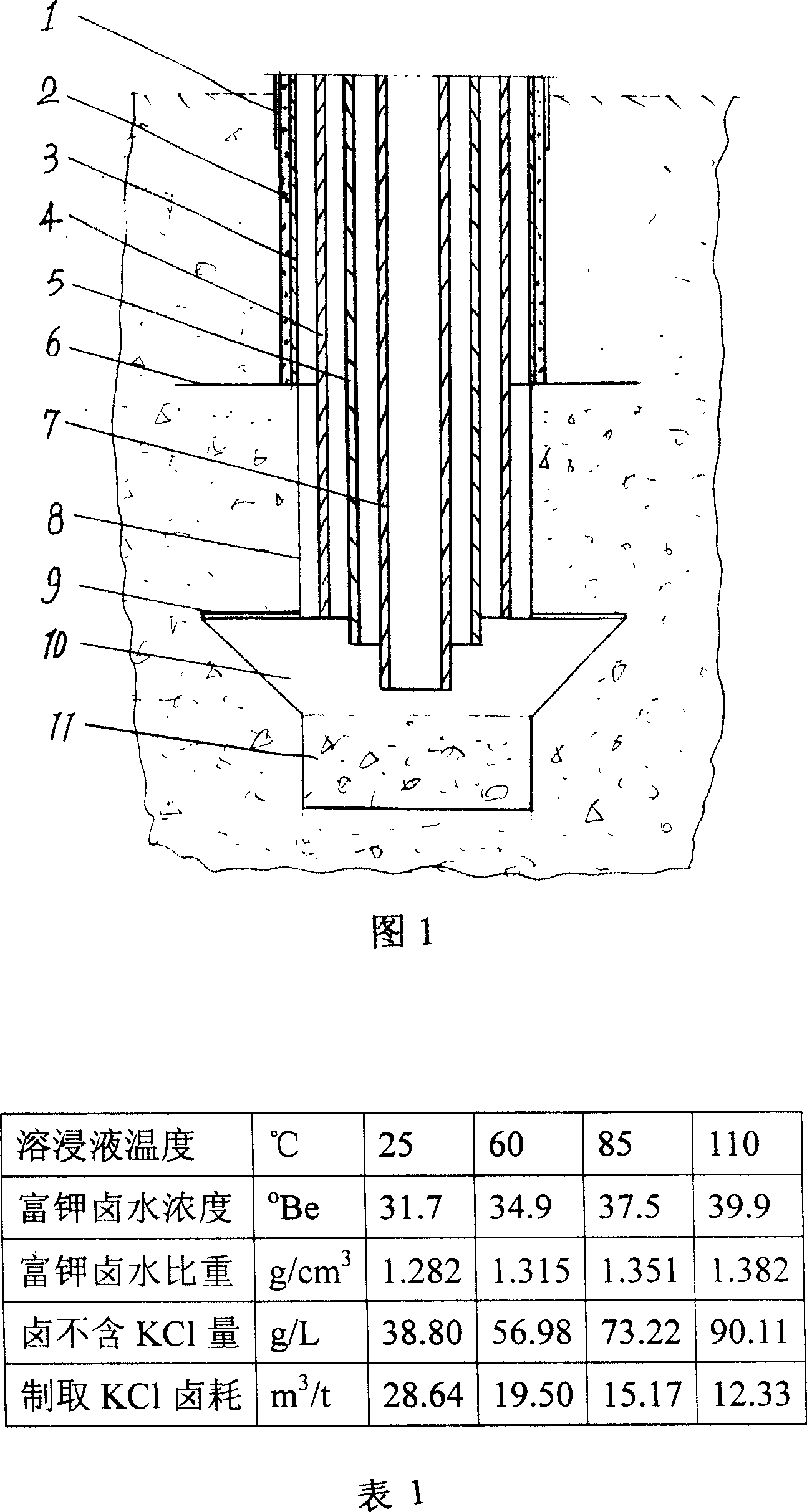
[0027] As shown in Figure 1, the outer layer of the underground drilling well wall 8 is equipped with a surface casing 1, and a cementing pipe 3 is installed in the surface casing 1, and a water ring 2 is set between the surface casing 1 and the cementing pipe 3, and the cement The lower end of the ring 2 and the cementing pipe 3 is provided with a safety roof pillar 6, which is used for cementing to prevent the overburden from collapsing and preventing water leakage in the well. At the same time, the liquid anti-emulsifier pad is sent into or out of the well through the cementing pipe 3 layer, a liftable leaching solution pipe 4 is installed in the cementing pipe 3, the lower end of which extends to the top of the salt tank 10, and the upper port is connected with the leaching solution delivery pipeline, one can transport the leaching solution into the well, and the other One is that when the central brine pipe 7 is blocked, potassium-rich brine can be transported to the groun...
Embodiment 2
[0029] A. With 5m 3 The flow rate per hour and the injection pressure of 2MPa send the paraffin liquid as an anti-emulsifier into the salt tank at the bottom of the underground ore layer through the cementing pipe, and form a liquid cushion in the salt tank;
[0030] B. As the immersion liquid, the aqueous solution saturated with NaCl at normal temperature and with a MgCl content of 10 mg / liter was dissolved in 5 m 3 The flow rate per hour and the pressure of 2MPa are sent to the lower part of the liquid cushion in the downhole salt tank through the immersion liquid pipe, and at the same time, the 3 The flow rate per hour and the pressure of 3MPa send steam to the lower part of the liquid cushion in the underground salt tank through the steam pipe to dissolve the bottom ore;
[0031] C. The dissolved ore liquid is less than 5m 3 The flow rate per hour and the pressure less than 1MPa are mined to the ground through the central brine extraction pipe, and the undissolved halite...
Embodiment 3
[0035] A. With 15m 3 / h flow rate, 5MPa injection pressure, the diesel oil used as an anti-emulsifier is sent into the salt tank at the bottom of the underground ore layer through the cementing pipe, and a liquid cushion is formed in the salt tank;
[0036] B. Saturating NaCl at room temperature as the immersion solution, and using an aqueous solution with a MgCl content of 20 mg / liter at 50 m 3 The flow rate per hour and the pressure of 4MPa are sent to the lower part of the liquid cushion in the downhole salt tank through the immersion liquid pipe, and at the same time 3The flow rate per hour and the pressure of 10MPa send steam to the lower part of the liquid cushion in the downhole salt tank through the steam pipe to dissolve the bottom ore;
[0037] C. The dissolved ore liquid is less than 50m 3 The flow rate per hour and the pressure less than 1MPa are mined to the ground through the central brine extraction pipe, and the undissolved halite minerals are filled at the b...
PUM
 Abstract
Description
Claims
Application Information