Aeroplane oil box leakage source checking device

A detection device and aircraft fuel tank technology, which is applied in the direction of measuring the rate of increase and deceleration of the fluid, using liquid/vacuum degree to measure the liquid tightness, etc., can solve the inconvenient use and adjustment, the difficulty of detecting the exact position of the internal leakage point, and the structure of the fuel tank Seal damage and other problems, to achieve the effect of easy processing and assembly, simple and convenient structure, and low manufacturing cost

Inactive Publication Date: 2007-07-04
中国民用航空学院
View PDF0 Cites 6 Cited by
  • Summary
  • Abstract
  • Description
  • Claims
  • Application Information

AI Technical Summary

Problems solved by technology

At present, there are many kinds of leak detection methods at home and abroad, and the commonly used methods are generally as follows: visual method, talcum powder method, backflush method, pressurization method, vacuum method, hollow rivet method, leakage path closure method, helium Gas method, etc., each method has its own defects-either the effect is not obvious, or the leak detection equipment is too expensive, inconvenient to use and adjust, or it is harmful to the structure of the fuel tank itself
For example: the blowback method requires good cooperation and patience from the blower and the searcher, but the influence of human factors is relatively large, and if the leakage path is t

Method used


Image

  • Aeroplane oil box leakage source checking device
  • Aeroplane oil box leakage source checking device

Examples


Example Embodiment

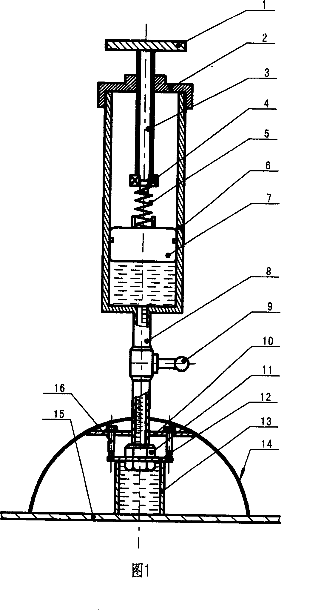
[0021] Embodiment 1: The aircraft fuel tank leakage point detection device is provided with hydraulic power by the liquid supply cylinder 6, an oil pipe 8 is connected to the oil outlet of the liquid supply cylinder, and a pressure gauge 9 is installed on the oil pipe. The oil pipe passes through the negative pressure cover 14 and fixes a sealing cover plate 12 in a threaded manner through the upper and lower screw nuts 11 on the outer edge of the end of the oil pipe. Under this sealing cover plate, the leak detection box 13 is axially fixed, and its sealing method is to paste the nut and the leak detection box together with glue to play a sealing role. Negative pressure cover and leak detection box are all placed on the aircraft fuel tank 15. A pressure regulating ring plate 10 is fixed axially upward in the negative pressure cover through the struts 16 uniformly distributed and fixed on the outer edge of the sealing cover plate, and the pressure regulating ring is supported ...

Example Embodiment

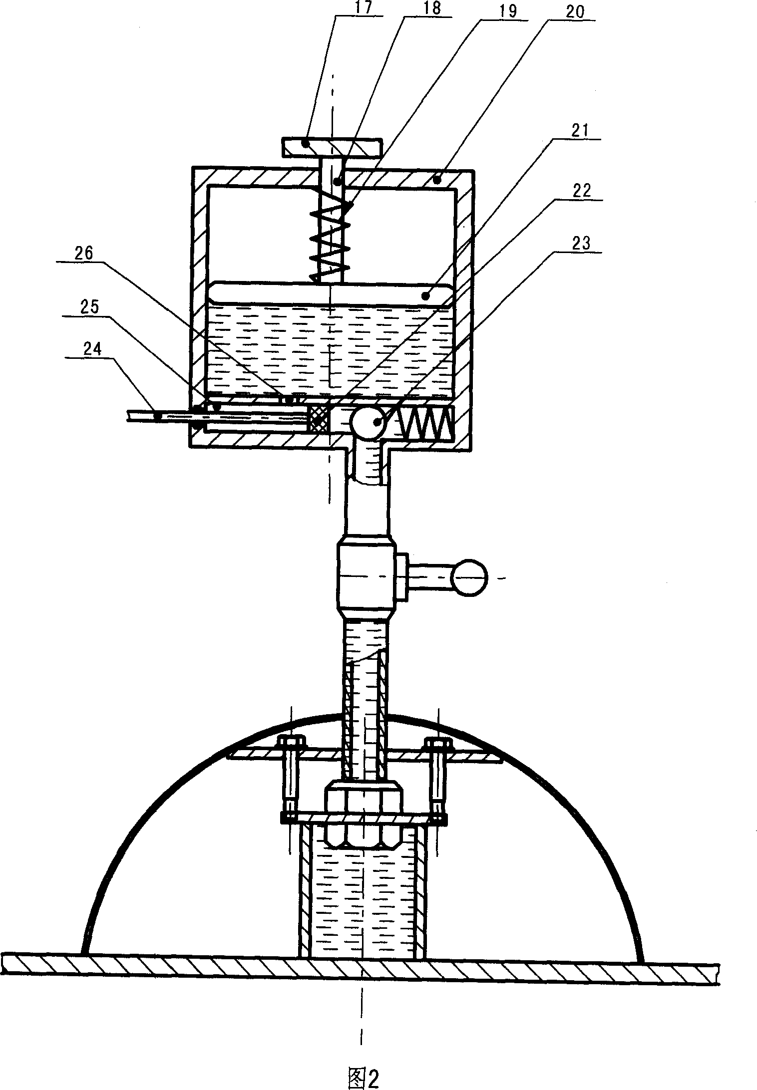
[0025] Embodiment 2: The difference between this embodiment and Embodiment 1 is only in the configuration of the liquid supply cylinder. The structure of the liquid supply cylinder is as follows: a liquid supply cavity 25 connected to the oil pipe is provided at the bottom of the liquid supply cylinder 20 , a one-way valve 23 is installed at the communication part between the liquid supply chamber and the oil pipe, the liquid supply chamber is connected to the liquid supply cylinder through the oil inlet 26, and an oil injection piston 22 runs in the liquid supply chamber, and the oil injection piston is connected through the valve stem 18 Valve rod 24 outside the oil supply cylinder. A buffer spring 19 and a pressure handle 17 are axially installed on the piston 21 of the liquid supply cylinder.

[0026] Other structures of Embodiment 2 are the same as those of Embodiment 1, and will not be repeated here.

[0027] The working principle of the liquid supply cylinder in this e...


PUM


Abstract

The invention belongs to leak detection equipment of airplane tank. The main characteristics of technique are that: the oil pipe passes through the negative pressure cover and the edges of oil pipe are mounted on the sealed cover, the sealed cover seals the leak detection box along the axial direction, the outer edges of the sealed cover fix the pressure regulation annular plate in the negative pressure cover along the supporting pole direction, the oil pipe connects with the oil cylinder. The invention can detect the inner missing dots according to the outer missing dots quickly and efficiently (the reverse is true), it has advantages of simplicity, intuitionistic, high efficiency and nicety, and the liquid pressure can be adjusted according to the requirement.

Description

technical field [0001] The invention belongs to a leakage detection device, in particular to a leakage point detection device for aircraft oil tank leakage. Background technique [0002] Due to the complex structure of aircraft fuel tanks, different leak detection methods are applied depending on the area where the leakage occurs, the environment and the working conditions of the site. At present, there are many kinds of leak detection methods at home and abroad, and the commonly used methods are generally as follows: visual method, talcum powder method, backflush method, pressurization method, vacuum method, hollow rivet method, leakage path closure method, helium Various methods, such as gas method, have their own defects—either the effect is not obvious, or the leak detection equipment is too expensive, inconvenient to use and adjust, or it may damage the structure of the fuel tank itself. For example: the blowback method requires good cooperation and patience from the b...

Claims


Application Information

Patent Timeline
IPC IPC(8): G01M3/26G01M3/32
Inventor 祝世兴杨永红
Owner 中国民用航空学院
Why Eureka
Try Eureka