Input voltage sensing circuit

An input voltage, detection circuit technology, applied in the direction of DC power input conversion to DC power output, electrical components, adjusting electrical variables, etc., can solve the problems of large RC delay, low power consumption, and difficult to obtain resistance, and achieve fast and The effect of accurate detection, low-cost solution

Inactive Publication Date: 2007-07-04
INTERNATIONAL RECTIFIER COEP
View PDF0 Cites 10 Cited by
  • Summary
  • Abstract
  • Description
  • Claims
  • Application Information

AI Technical Summary

Problems solved by technology

The drawback is that the RC delay is still large, because to balance the power dissipated in resistor R1 with the RC time constant, a larger va

Method used


Image

  • Input voltage sensing circuit
  • Input voltage sensing circuit
  • Input voltage sensing circuit

Examples


Embodiment Construction

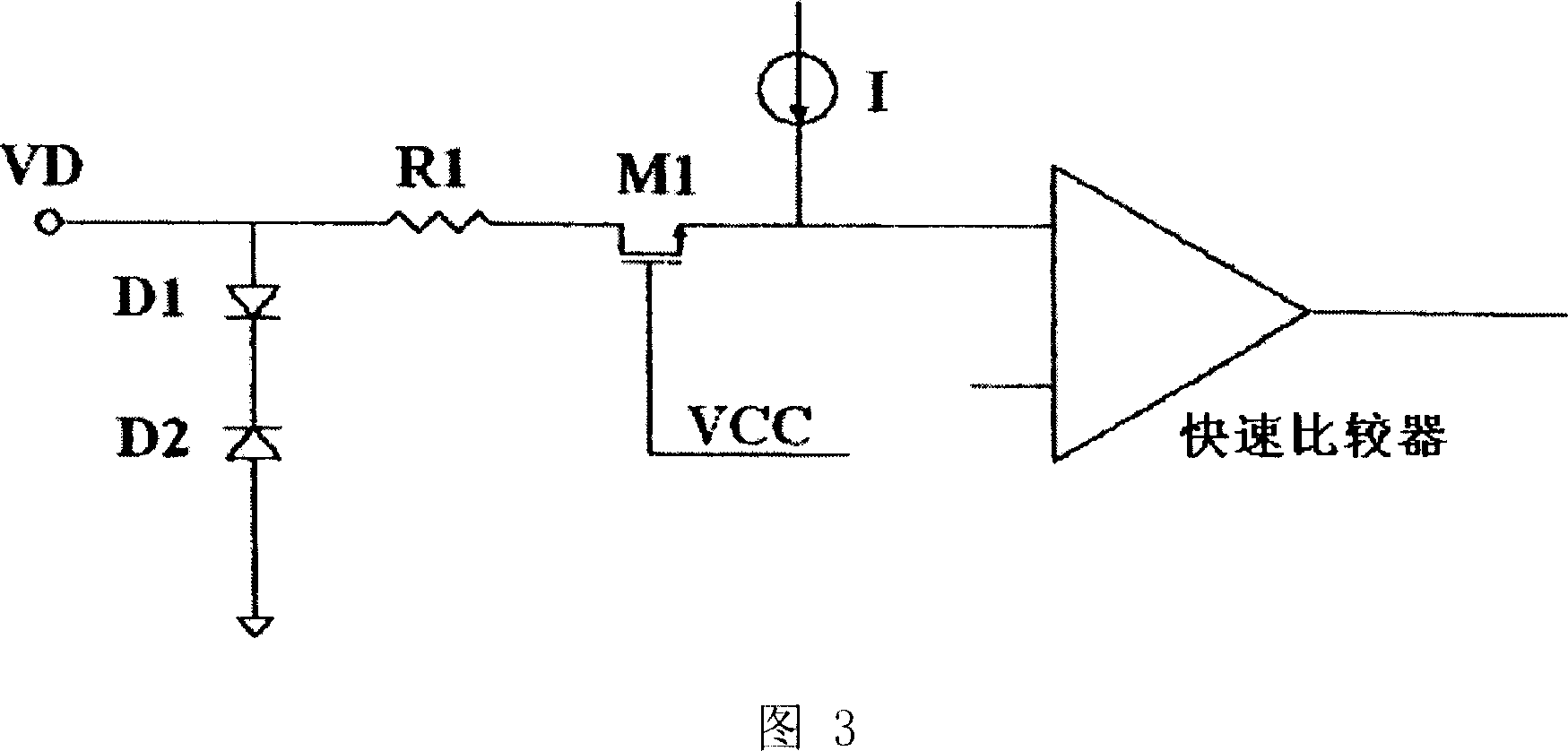
[0017] Referring now to the drawings, FIG. 3 shows an input voltage detection circuit according to the present invention. The transistor M1 is a high voltage Metal Oxide Semiconductor Field Effect Transistor (MOSFET), such as (N-Type Field Effect Transistor) NMOS. When the input voltage is higher than VCC and reaches the drain breakdown voltage, for example greater than 200V, it turns off itself to protect the low voltage input of the fast comparator (COMP).

[0018] Reversely coupled diodes D2 and D1 form a high voltage ESD protection circuit. D2 may include a high voltage termination diode. It has two functions: forming a high voltage ESD device (eg 200 volts) and providing a high voltage substrate for resistor R1. In this way, resistor R1 will be just a normal low voltage polysilicon resistor instead of a high voltage resistor, and it will not affect the accuracy of the detection.

[0019] Diode D1 may comprise a low voltage diode for blocking the path of the ESD circuit...


PUM


Abstract

An input voltage sensing circuit comprising a circuit input terminal; a comparator having first and second input terminals, the first of said input terminals being coupled to a reference voltage; a switch circuit provided between the circuit input terminal and the second of the input terminals of the comparator, the switch being provided to protect the comparator from voltages exceeding a predetermined voltage at which the switch turns off; and an electrostatic discharge circuit coupled to the circuit input terminal for discharging electrostatic induced voltages exceeding a predetermined value.

Description

[0001] related application [0002] This application claims priority to US Provisional Application 60 / 751,912, filed December 20, 2005, entitled "INPUT VOLTAGE SENSING CIRCUIT," the entire disclosure of which is hereby incorporated by reference. Background technique [0003] The present invention relates to a detection circuit, in particular to a detection circuit which detects a voltage with a wide dynamic voltage range from negative voltage to very high positive voltage and can accurately and quickly detect crossing a threshold. [0004] The requirement for this type of circuit is that the input signal range is wide, and it must be able to accept a wide range of input signals without damaging the circuit. For example, a signal range from minus 10 volts to 200 volts is within the scope of application of the present invention. Also, the input stage must have very little delay, the threshold detection must be very accurate and the input must be electrostatic discharge (ESD) pr...

Claims


Application Information

Patent Timeline
IPC IPC(8): H02M3/156H02M1/08
Inventor I·米雷亚M·苏布拉马尼亚曼
Owner INTERNATIONAL RECTIFIER COEP
Why Eureka
Try Eureka