Mobile contact line of electrified railway

A technology of electrified railway and catenary, applied in the direction of overhead lines, etc., can solve the problems of heavy maintenance workload, low fuel utilization rate, high operating cost, etc., and achieve the effect of small maintenance workload, high driving speed and low operating cost

Active Publication Date: 2007-07-11
CHINA RAILWAY FIRST SURVEY & DESIGN INST GRP
View PDF0 Cites 24 Cited by
  • Summary
  • Abstract
  • Description
  • Claims
  • Application Information

AI Technical Summary

Problems solved by technology

[0002] At present, the trains in the electrified traction section of the railway enter the cargo loading and unloading line or enter the warehouse for inspection and maintenance are basically completed by internal combustion regulators, so the disadvantages are as follows: 1. This kind of operation method uses fuel oil as power, because the fuel oil cannot be fully burned and the exhaust gas is discharged into the atmosphere, so It does not conform to the national energy policy and is not conducive to environmental protection; 2. It is necessary to purchase additional regulators, special parking lines, maintenance facilities for internal combustion regulators, etc., and the investment is large; 3. Before electric traction trains enter the operation line, they must be replaced with internal combustion regulators , After the operation, the internal combustion engine must be replaced by an electric locomotive, so the operation efficiency is low; 4. The fuel utilization rate is low, the dedicated maintenance facilities, and the dedicated driver are on duty for 24 hours, and the operating cost is high.
Although some loading and unloading lines or maintenance garages have realized electrified hanging nets, most of them are in a static mode. A small number of maintenance garages have adopted rigid horizontal rotating moving catenary, and the moving catenary is hung on the wall of the garage, which has high requirements for the settlement of the subgrade foundation. , it is difficult to meet the requirements for outdoor subgrade settlement, and at the same time, the span is small, generally 10m, and the investment is relatively large. In addition, the power is dispersed, the synchronization is difficult to guarantee, and the maintenance workload is large; At the coal funnel, the method of horizontal suspension or upturning is adopted, and the catenary is a simple suspension method, which allows low driving speed and short moving sections, the longest of which is only about 150m, and the catenary constantly changes geometry during the movement process. Therefore, the catenary has serious fatigue, poor safety, short service life, heavy maintenance workload and high operating cost

Method used


Image

  • Mobile contact line of electrified railway
  • Mobile contact line of electrified railway
  • Mobile contact line of electrified railway

Examples


Embodiment Construction

[0032] Below in conjunction with specific embodiment, the present invention is described further:

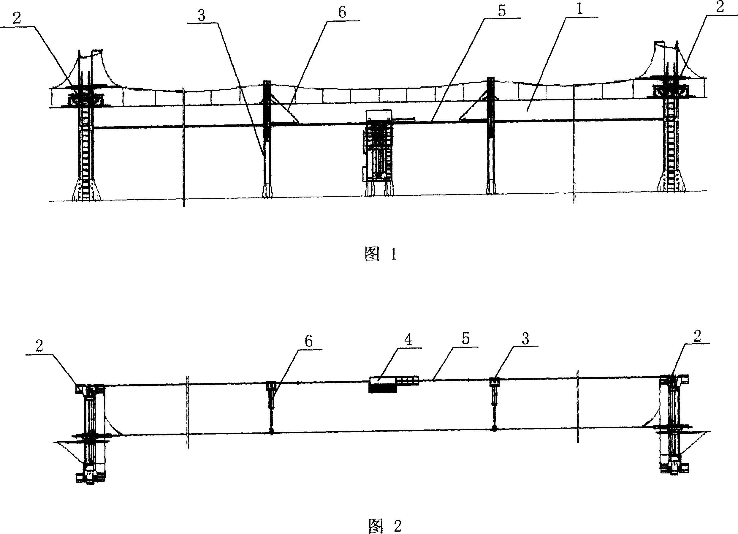
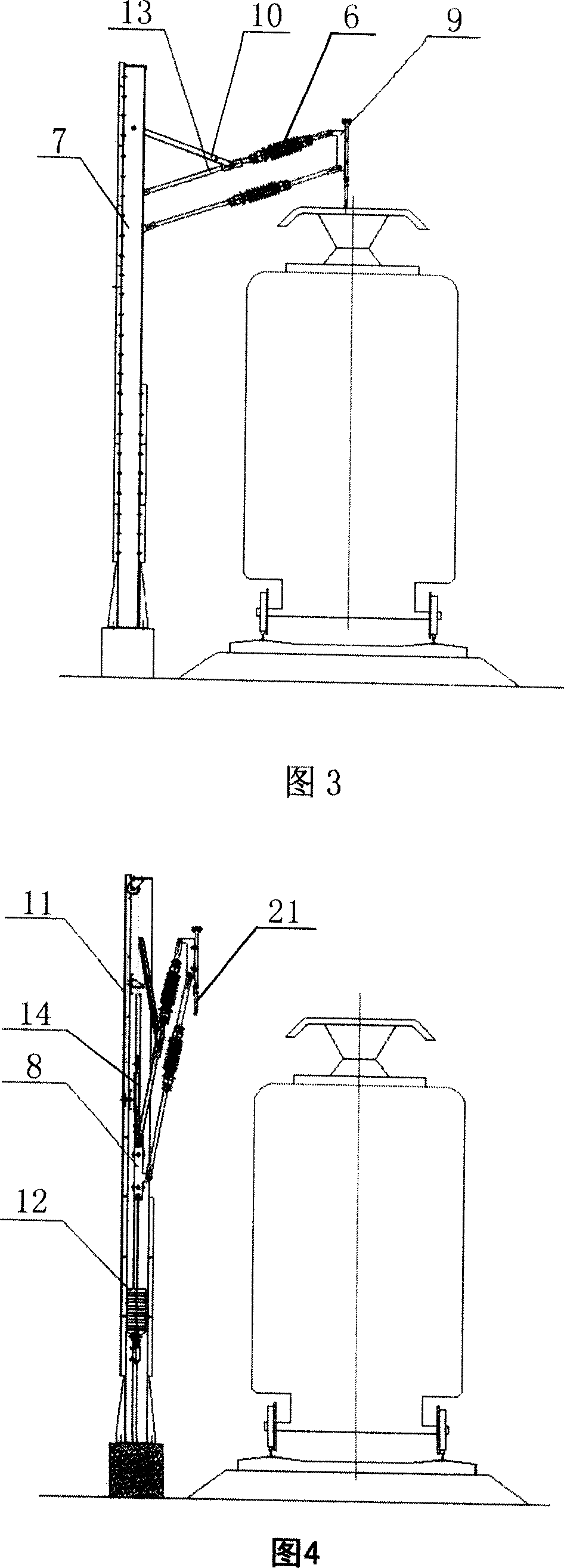
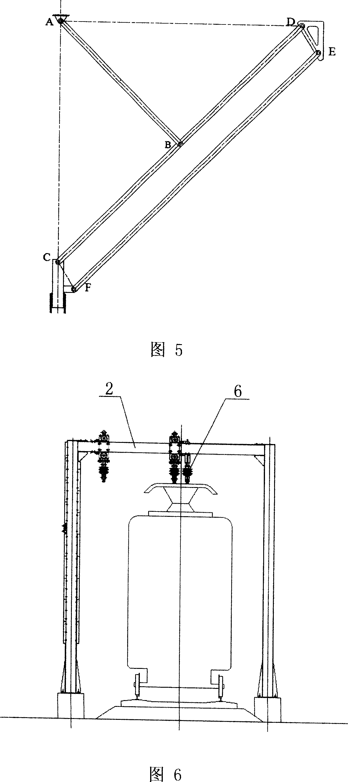
[0033] Referring to Fig. 1 and Fig. 2, Fig. 1 is a schematic diagram of the overall structure of the movable catenary of the electrified railway of the present invention; Fig. 1 is a top view of the overall structure of the present invention; the movable catenary of the electrified railway adopts a flexible simple chain suspension full compensation catenary structure ; It consists of a translation arm support device 3 equipped with a parallelogram combined arm arm with a crank slider mechanism, a transition section gantry 2 with a compensation walking device for the anchor section, a pulley type tension spring compensation device 20, and an elastic suspension locator 21 etc.; the overall translation of the catenary is driven by the motor 4 installed on the traction power frame through the traction steel rope 5.

[0034] The scope of the loading and unloading operation area is de...


PUM


Abstract

The invention relates to a railway movable contact network, wherein the inventive contact network uses chain suspension method, suspended on movable support; the support comprise two end anchor joint door supports and several supports with parallelogram joints and crank blocks between door supports. The invention can draw motor to translate the contact network. Since the shape of contact network will not change, it can obtain high driving speed and long service life.

Description

Technical field: [0001] The invention relates to an electrified railway catenary, specifically a movable catenary for an electrified railway, which is a flexible catenary that adopts a parallelogram four-bar linkage mechanism to move horizontally. In this mode, the catenary adopts a chain suspension method. The requirements for the foundation are loose, and the geometry of the catenary will not change during the movement, allowing high driving speeds. Background technique [0002] At present, the trains in the electrified traction section of the railway enter the cargo loading and unloading line or enter the warehouse for inspection and maintenance are basically completed by internal combustion regulators, so the disadvantages are as follows: 1. This kind of operation method uses fuel oil as power, because the fuel oil cannot be fully burned and the exhaust gas is discharged into the atmosphere, so It does not conform to the national energy policy and is not conducive to env...

Claims


Application Information

Patent Timeline
Patent Type & Authority Applications(China)
IPC IPC(8): B60M1/20
Inventor 汪吉健陈志隋延民田志军王玉环熊敏强余杨武寇宗乾李晋宫衍圣何廷文刘长利万一农韩佳栋宋颖曹毅
Owner CHINA RAILWAY FIRST SURVEY & DESIGN INST GRP
Why Eureka
Try Eureka