
Mid-board pluggable optical devices, assemblies, and methods

a technology of optical devices and assemblies, applied in the direction of coupling device connections, instruments, electrical equipment, etc., can solve the problems of inability to achieve msa consensus, inability to efficiently mitigate equipment, and new transceiver form factors, etc., to improve spatial efficiency and security of optical fiber management and transceiver-to-optical fiber connectivity, reduce power consumption, and improve the effect of spatial efficiency and security

Active Publication Date: 2018-07-03
CIENA
View PDF2 Cites 10 Cited by
  • Summary
  • Abstract
  • Description
  • Claims
  • Application Information

AI Technical Summary

Benefits of technology

The present invention is a pluggable transceivers system that improves the efficiency and security of optical fiber management and transceiver-to-optical fiber connectivity. By moving the housing of the pluggable transceivers and connected fibers away from the faceplate of the chassis that hosts the motherboard\processor(s), the system achieves better spatial efficiency and security of optical fiber management. The delivery of traffic to one or many connected motherboard\processor(s) using aggregate electrical interface(s) per motherboard\processor chassis, instead of via many individual optical interface\fiber per remote data networking equipment ports, is a more robust and spatially efficient point of interconnect. The system also allows for a modular and variable ratio of pluggable transceivers to motherboard\processor(s) that is not bound by each motherboard / processor chassis faceplate surface area, and enables improved data center rack design. Overall, the system improves the efficiency and security of optical fiber management and transceivers in data centers without requiring a change in the transceiver form factor or MSA consensus.

Problems solved by technology

MSA consensus takes time and requires early adoption, which costs may not enable.
A new transceiver form factor does not necessarily efficiently mitigate equipment faceplate surface area as a bottleneck to the number of hosted transceivers and, therefore, delivered traffic per second.
The development of a card that can interface with a long list of possible far end standards is likely not affordable for most manufacturers.
The acceptance of a card implementing a requirement for a rigid set of far end attributes would likely not offer sufficient deployment flexibility to gain industry adoption.
Further, data rates are constrained by industry adoption and limits imposed by physics.
Current solutions do not enable the strategic positioning of the aggregate housing of transceiver interfaces, such as at the top or bottom position of a rack so as to mitigate the extension of fiber deployment within the rack.
Thus, current solutions do little to mitigate the space consumption and cost of the fiber itself.
Further, current solutions do not make modular the relationship between a potentially “infinite” pool of aggregated transceiver interfaces with any number of data traffic motherboard\processor chassis based upon interconnection and bandwidth requirements.

Method used


Image

  • Mid-board pluggable optical devices, assemblies, and methods
  • Mid-board pluggable optical devices, assemblies, and methods
  • Mid-board pluggable optical devices, assemblies, and methods

Examples


Embodiment Construction

[0024]Again, the faceplates of conventional data networking systems are typically very crowded with port density. As port density increases, conventional modular designs primarily focus on one insertion method. SFPs slide into a rack along a horizontal plane perpendicular to the faceplate. The SFPs protrude slightly from the faceplate and the optical fibers connect to this protruding portion of the SFPs. Electrical connections are made via horizontal connections at the back of the SFPs. The use of more SFPs, more optical fibers, and more electrical connections provides more capacity, at the expense of faceplate space, including long entanglements of optical fiber.

[0025]Some conventional designs get around faceplate density issues by using mid-board optics (MBOs). This frees up space on the faceplate, allowing the user to implement specialized high density optical connectors. The disadvantage to MBOs is that the end customer essentially loses the modularity of SFPs. With MBOs, one ca...


PUM


Abstract

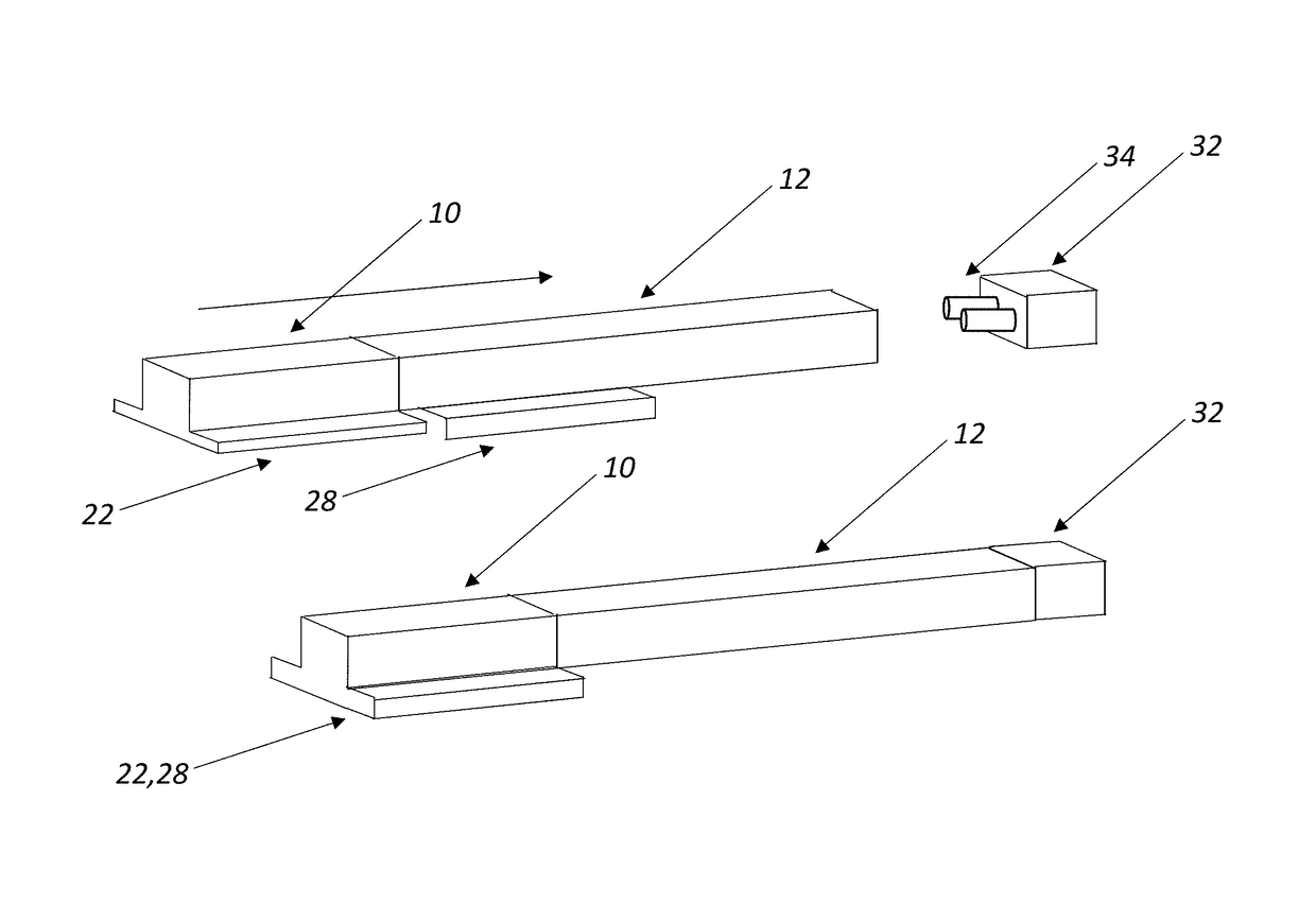
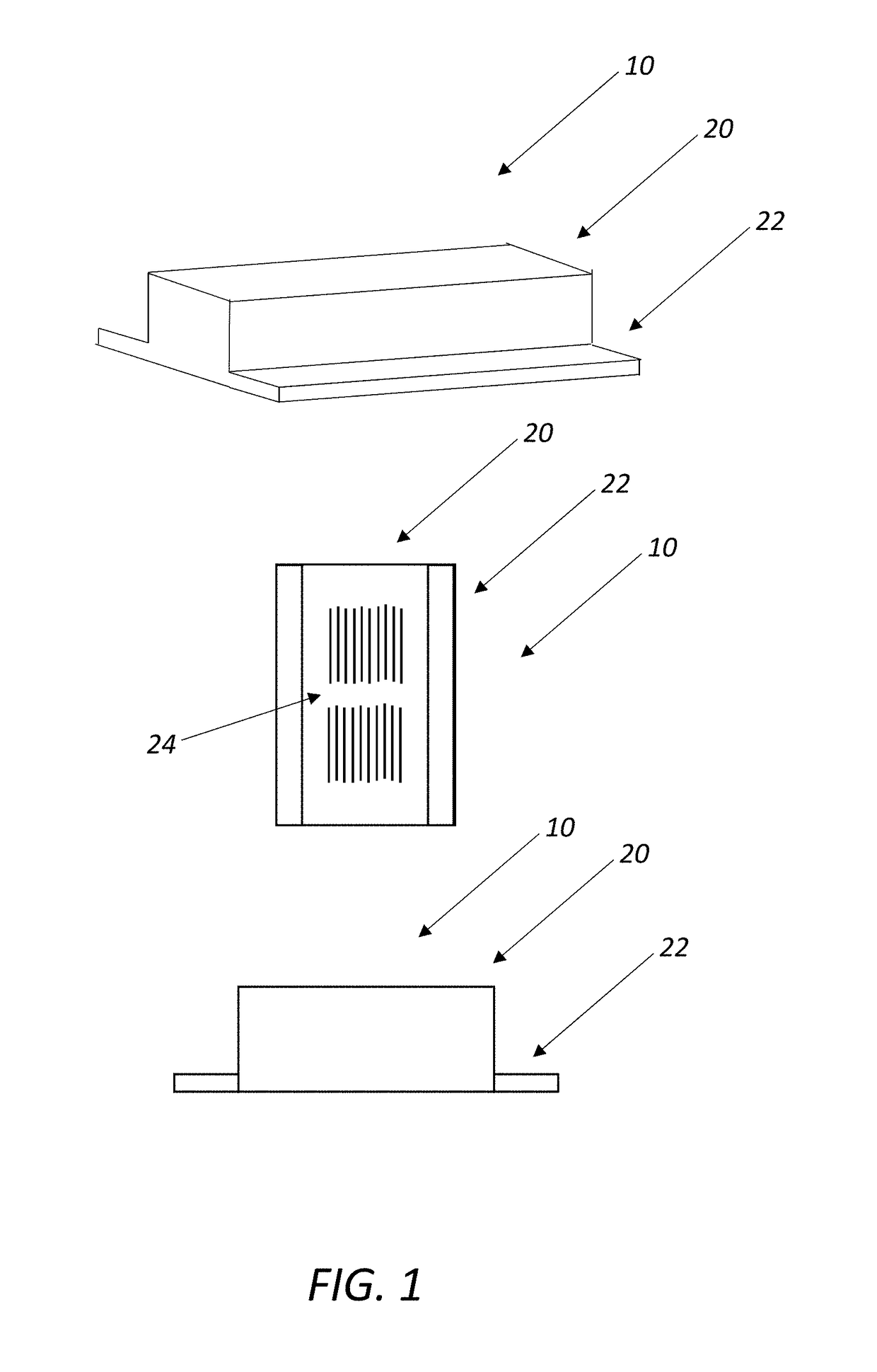
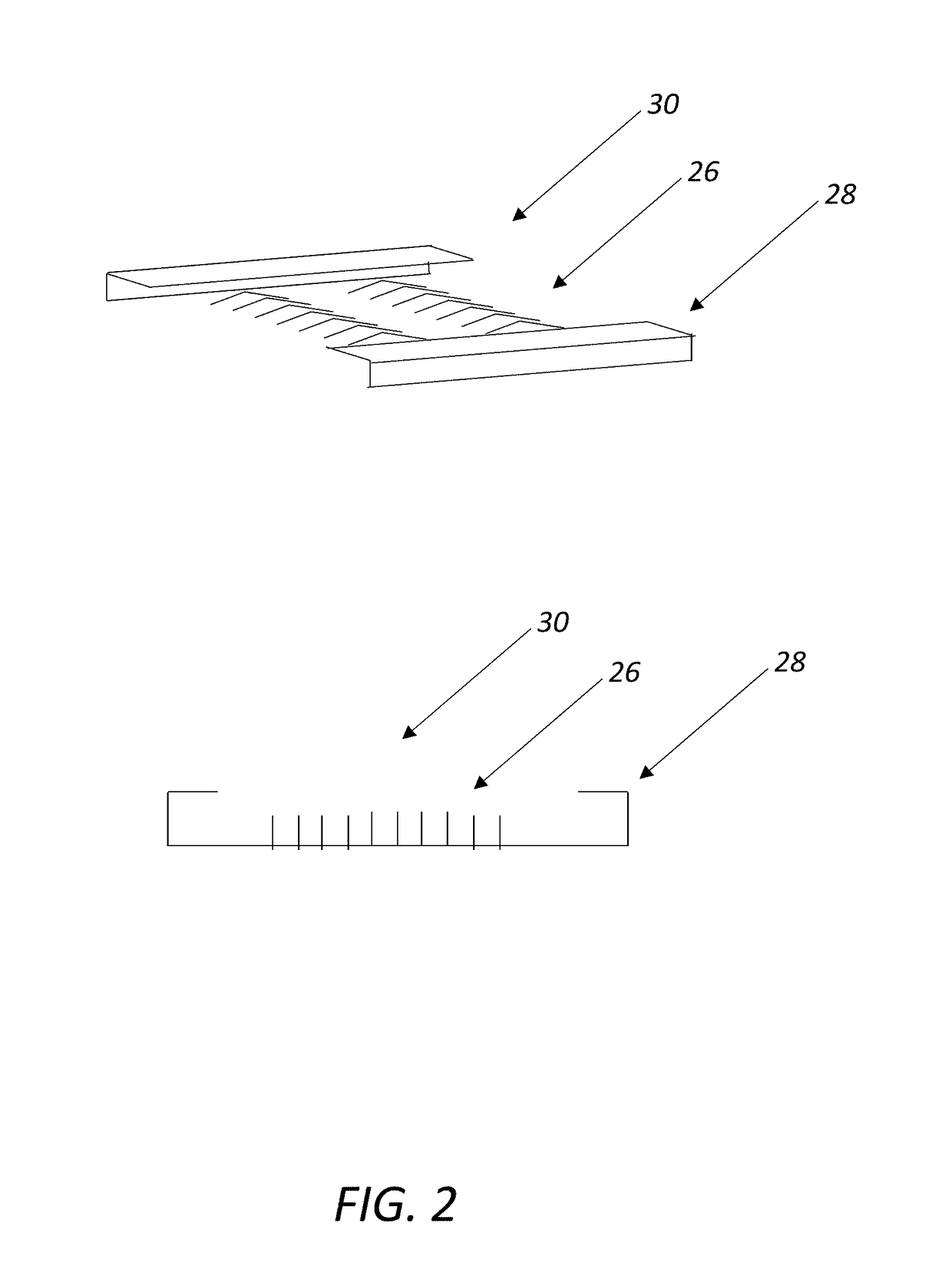
A pluggable optical module, including: a pluggable module unit including an optical connector disposed at a front end portion thereof and an electrical connector disposed at a rear bottom portion thereof, wherein the optical connector is configured to be optically coupled to an optical fiber, and wherein the electrical connector is configured to be electrically coupled to an electrical connector disposed on an electrical board. Optionally, the pluggable module unit includes a pluggable module adapter secured to a pluggable module body. The electrical connector is then disposed at a rear bottom portion of the pluggable module adapter. A pluggable optical module aggregator, including: a housing; an electrical board; a plurality of electrical connectors and a bulk electrical connector consolidating and terminating the plurality of electrical connectors and accessible from the exterior of the housing; and a plurality of optical connectors and a bulk optical connector consolidating and terminating the plurality of optical connectors and accessible from the exterior of the housing.

Description

FIELD OF THE INVENTION[0001]The present invention relates generally to optical networking systems and methods. More specifically, the present invention relates to mid-board pluggable optical devices, assemblies, and methods.BACKGROUND OF THE INVENTION[0002]Data centers are required to move petabits of data per second, demands are constantly growing, and costs must continuously be contained in order for operations to be profitable. Space and power are key monetization considerations within data centers, driving a need for improved efficiency in the delivery of data over status quo data networking equipment designs. It would seem that data networking equipment manufacturers would take the following approaches: 1) seek multi-source agreement (MSA) consensus regarding the implementation of the reduction in size of existing transceiver pluggable form factors so as to implement improved port density of data networking gear faceplates; 2) develop new optical interface cards, cables, and co...

Claims


Application Information

Patent Timeline
Patent Type & Authority Patents(United States)
IPC IPC(8): G02B6/42G02B6/38H01R31/06
CPCG02B6/4292G02B6/3814H01R31/06G02B6/4278G02B6/3817G02B6/426
Inventor RIVAUD, DANIELESTABROOKS, KEVINVANDERYDT, GREGORY
Owner CIENA
Learn More