PDMS-based ligands for quantum dots in silicones

a technology of silicone and ligands, which is applied in the field of pdms-based ligands for quantum dots in silicones, can solve the problems of poor process ability, poor stability of qd powders (without matrix), and poor stability of qd powders in high blue light flux, and achieves high quality, high interest in lighting applications, and narrow emission band

Active Publication Date: 2018-07-31
LUMILEDS
View PDF41 Cites 4 Cited by
  • Summary
  • Abstract
  • Description
  • Claims
  • Application Information

AI Technical Summary

Benefits of technology

[0005]Nano particles, such as quantum dots (QDs), have shown to be highly interesting in lighting applications. They could e.g. serve as inorganic phosphor in converting blue light to other colors and have the advantage of a relative narrow emission band and the advantage of color tunable by the size of the QDs to be able to obtain high quality pure white light.
[0009]Surprisingly, the inventors have found amongst others that by exchanging the native QD ligands of light converter nano particles by particular PDMS-alike ligands, QDs may become truly miscible with silicones and / or significantly improves miscibility with silicones when specific conditions are met. Further, there is advantageously no need to use significant amounts of additional solvents such as hexane and acetone, or other solvents to obtain a well miscible system.
[0017]Such light converter, obtainable by the herein described process, may show luminescence (when embedded in the matrix of cured siloxane polymers) with a high quantum yield and stability. Further, the light converter may be relatively temperature and / or photochemical stable and / or transparent. Further, with this process, nano particles may be dispersed in the polymer in a relative even way, without the substantial disadvantage of agglomeration.
[0047]Further, good results may be obtained with x1 / y1≥0.80, but in general better results, in the sense of stability and / or transmission (of the light converter) are obtained when x1 / y1≥0.95, such as x1 / y1≥1.2.
[0061]One example, such as derived from WO 2011 / 031871, of a method of manufacturing a semiconductor nanocrystal is a colloidal growth process. Colloidal growth occurs by injection an M donor and an X donor into a hot coordinating solvent. One example of a preferred method for preparing monodisperse semiconductor nanocrystals comprises pyrolysis of organometallic reagents, such as dimethyl cadmium, injected into a hot, coordinating solvent. This permits discrete nucleation and results in the controlled growth of macroscopic quantities of semiconductor nanocrystals. The injection produces a nucleus that can be grown in a controlled manner to form a semiconductor nanocrystal. The reaction mixture can be gently heated to grow and anneal the semiconductor nanocrystal. Both the average size and the size distribution of the semiconductor nanocrystals in a sample are dependent on the growth temperature. The growth temperature necessary to maintain steady growth increases with increasing average crystal size. The semiconductor nanocrystal is a member of a population of semiconductor nanocrystals. As a result of the discrete nucleation and controlled growth, the population of semiconductor nanocrystals that can be obtained has a narrow, monodisperse distribution of diameters. The monodisperse distribution of diameters can also be referred to as a size. Preferably, a monodisperse population of particles includes a population of particles wherein at least about 60% of the particles in the population fall within a specified particle size range. A population of monodisperse particles preferably deviate less than 15% rms (root-mean-square) in diameter and more preferably less than 10% rms and most preferably less than 5%.

Problems solved by technology

A QD powder (without matrix) is not desired because of both concentration quenching effects and poor process ability of such a pure QD powder.
Currently, acrylic matrices are mostly used as a matrix for QDs, but they are known for their poor stability towards high blue light fluxes.
However, QDs generally have a hydrophobic organic coating (in the form of ligands, generally extending from the outer surface of the QD) which make them incompatible with silicones: generally a turbid mixture is obtained when QDs are mixed with silicones caused by agglomeration of the QDs.
This is undesired because of concentration quenching effects, expected increased degradation effects, and an uncontrolled way of processing these films leading to spatial concentration variations.

Method used


Image

  • PDMS-based ligands for quantum dots in silicones
  • PDMS-based ligands for quantum dots in silicones
  • PDMS-based ligands for quantum dots in silicones

Examples


Embodiment Construction

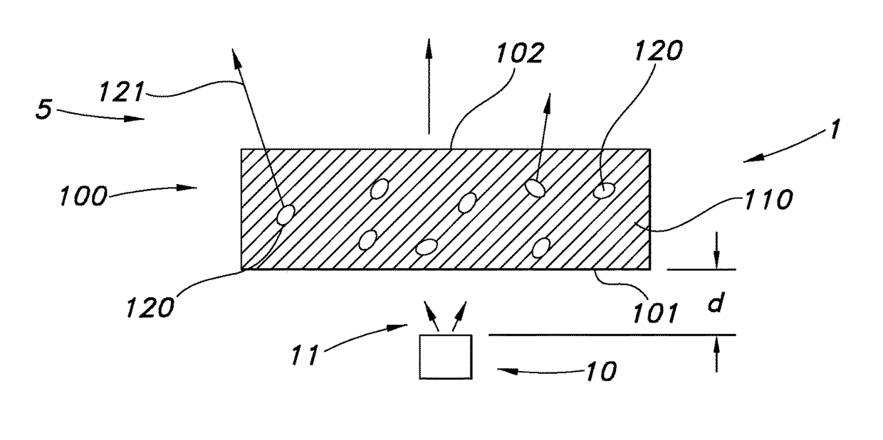
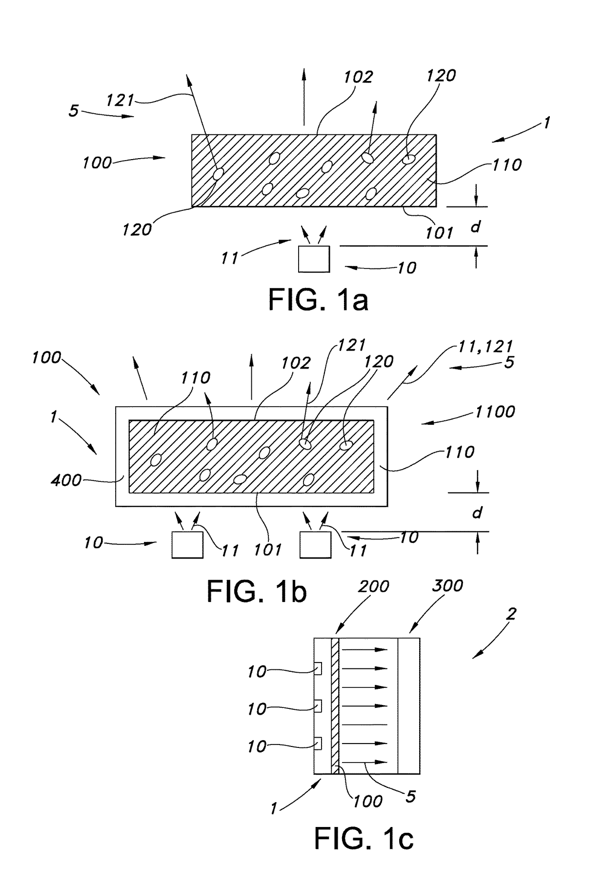
[0106]FIG. 1a schematically depicts a lighting device 1 comprising a light source 10 configured to generate light source light 11 and a light converter 100 configured to convert at least part of the light source light 11 into visible converter light 121. Here schematically only one light source 10 is depicted. However, more than one light source 10 may be present.

[0107]The light converter has an upstream side 101 (part of an external surface of the light converter), which is at least partly directed to the light source 10, and a downstream side 102 (part of an external surface of the light converter), which faces away from the light source 10 (in this transmissive configuration).

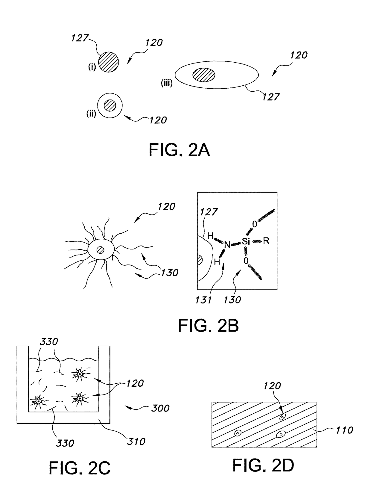
[0108]The light converter 100 comprises a polymeric host material 110 with light converter nanoparticles 120 embedded in the polymeric host material 110. These can be dots, rods, a combination thereof, etc. (see also above). The light converter nanoparticles 120 generate upon excitation by the light source l...


PUM

PropertyMeasurementUnit
particle sizeaaaaaaaaaa

Abstract

The invention provides a process for the production of a light converter comprising a siloxane polymer matrix with light converter nano particles embedded therein, the process comprising (a) mixing (i) light converter nano particles having an outer surface grafted with grafting ligands and (ii) curable siloxane polymers, and (b) curing the curable siloxane polymers, thereby producing the light converter; wherein the grafting ligands comprise siloxane grafting ligands having x1 Si backbone elements, wherein at least one Si backbone element of each siloxane grafting ligand comprises a side group having a grafting functionality; wherein the curable siloxane polymers have y1 Si backbone elements; and wherein x1 is at least 20, wherein y1 is at least 2, and wherein x1 / y1≥0.8.

Description

CROSS-REFERENCE TO PRIOR APPLICATIONS[0001]This application is the U.S. National Phase application under 35 U.S.C. § 371 of International Application No. PCT / IB2013 / 059577, filed on Oct. 23, 2013, which claims the benefit of U.S. Patent Application No. 61 / 718,260, filed on Oct. 25, 2012. These applications are hereby incorporated by reference herein.FIELD OF THE INVENTION[0002]The invention relates to a process for the production of a polymer within the polymer embedded light converter nano particles, to a light converter thus obtained, and to a lighting unit comprising such (polymeric) light converter.BACKGROUND OF THE INVENTION[0003]The use of nano particles, such as quantum dots (QD), for lighting applications is known in the art. US20110240960, for instance, describes a light emitting device comprising a light emitting source, a first quantum dot wavelength converter disposed above the light emitting source, the first quantum dot wavelength converter comprising, a plurality of f...

Claims


Application Information

Patent Timeline
Patent Type & Authority Patents(United States)
IPC IPC(8): C08J5/00G02F1/1335C09K11/88C09K11/02B82Y40/00B82Y20/00
CPCC09K11/025C08J5/005C09K11/883G02F1/133603B82Y20/00B82Y40/00Y10S977/95G02F2001/133614Y02E10/52Y10S977/774Y10S977/779Y10S977/897C08J2383/06H01L33/501B82Y30/00C08K3/00C08L83/04C09K11/02G02F1/133614
Inventor KOOLE, ROELOFHIKMET, RIFAT ATA MUSTAFABAESJOU, PATRICK JOHNBOHMER, MARCEL RENELUB, JOHAN
Owner LUMILEDS
Why Eureka
Try Eureka