Motor apparatus and motor driving circuit

a technology of motor motors and driving circuits, applied in the field of high-performance motor apparatuses and motor driving circuits, can solve the problems of affecting the operation of the motor, so as to reduce the number of times, reduce the switching power loss of the transistor, and improve the operation speed of the motor module.

Active Publication Date: 2018-08-07
FAIRWAY ELECTRONICS
View PDF3 Cites 4 Cited by
  • Summary
  • Abstract
  • Description
  • Claims
  • Application Information

AI Technical Summary

Benefits of technology

[0011]Based on the above, in the motor apparatus and the motor driving circuit of the invention, the operating speed of the motor module is increased when the temperature of the bridge arm circuits is greater than or equal to the threshold temperature value, so as to reduce the number of times of turning on and off the transistors in the bridge arm circuits to reduce switching power loss of the transistors and thereby lower the temperature of the bridge arm circuits. Furthermore, the motor apparatus and the motor driving circuit disclosed in the embodiments of the invention use a non-contact type magnetic force sensing switch as the speed adjustment switch of the motor apparatus. Thus, when the motor apparatus vibrates due to operation, the non-contact type magnetic force sensing switch does not cause a spark due to the vibration, and therefore the motor apparatus has a longer service life and better waterproof and dustproof functions than a general motor apparatus with a contact type switch. Besides, the motor driving circuit performs the over-current protection with the larger first reference value in the start-up stage of the motor module, so as to avoid frequently triggering the over-current protection mechanism during start-up of the motor module, which results in longer time for start-up of the motor module. On the other hand, in the normal operation stage after the motor module has completed the start-up, the motor driving circuit performs the over-current protection with the smaller second reference value, so as to prevent the motor module from being damaged by an excessive current during the normal operation.

Problems solved by technology

However, when the power switch element is turned on or turned off in responds to transition of the pulse width modulation signal, frequently turning on and off the power switch element would result in switching power loss and raise the temperature of the power switch element.
When the temperature of the power switch element is too high, the power switch element may be stopped for cooling, but it will interrupt the operation of the motor.
Another common technique is to use a heat dissipation device for cooling the power switch element, but it will increase the production costs of the motor and such a technique is not suitable for a miniaturized motor apparatus.
However, when the motor apparatus vibrates due to operation, the contact electrodes in such contact type switches may be in poor contact due to the vibration, which may even cause a spark and cause the contact electrodes to be oxidized.
In addition, the motor apparatus with such contact type switches is generally inferior in terms of waterproof function, which also limits use of the motor apparatus.
Since the motor has a larger current at the time of start-up, if the preset current value is set too low, the over-current protection mechanism may be triggered frequently during the start-up and cause the start-up time of the motor to become longer.
On the other hand, if the preset current value is set too high, it may shorten the start-up time, but the risk of providing an excessive current to the motor also increases.

Method used


Image

  • Motor apparatus and motor driving circuit
  • Motor apparatus and motor driving circuit
  • Motor apparatus and motor driving circuit

Examples


Embodiment Construction

[0024]In order to make the invention more comprehensible, several embodiments are described below as examples of implementation of the invention. Moreover, elements / components / steps with the same reference numerals are used to represent identical or similar parts in the figures and embodiments where appropriate.

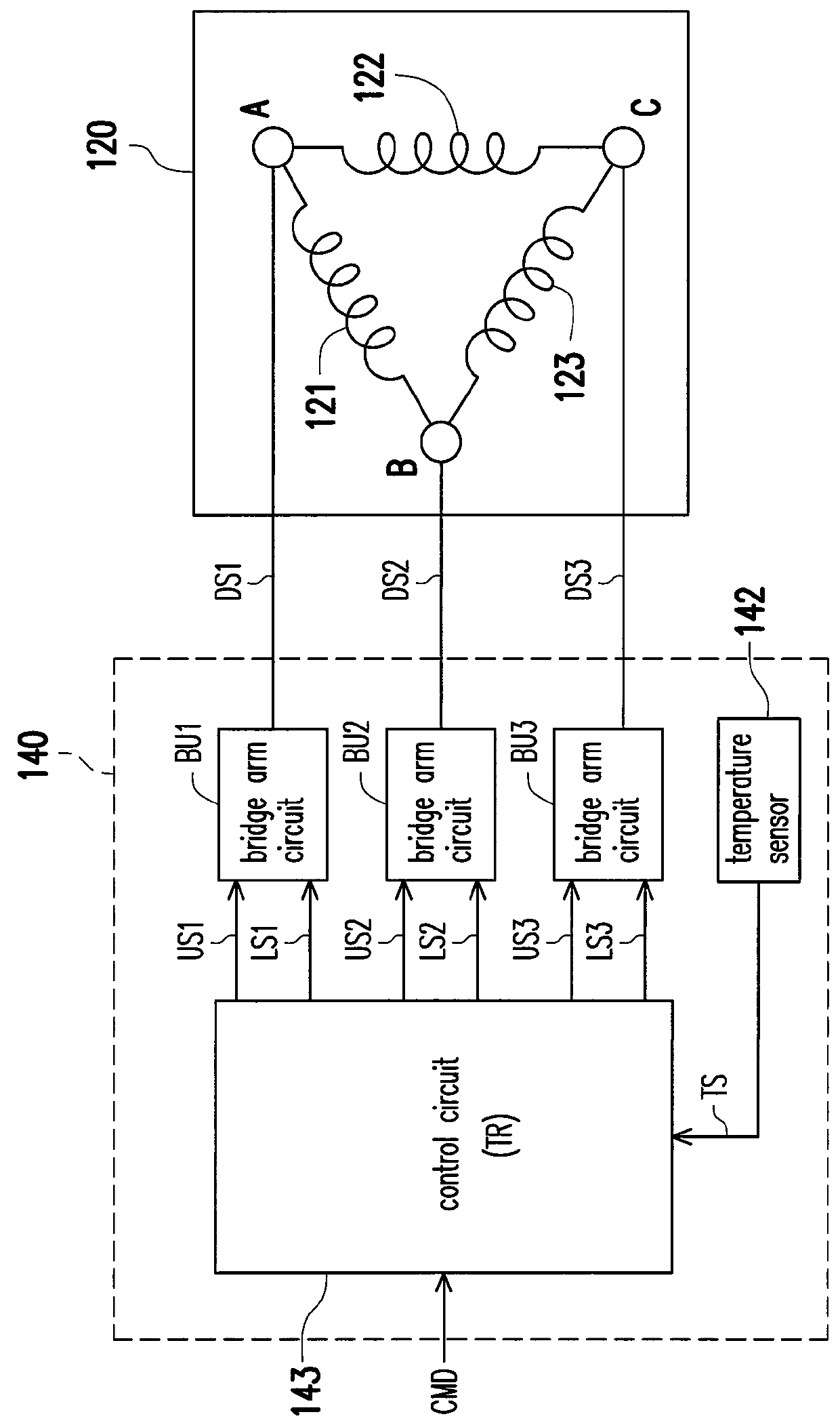
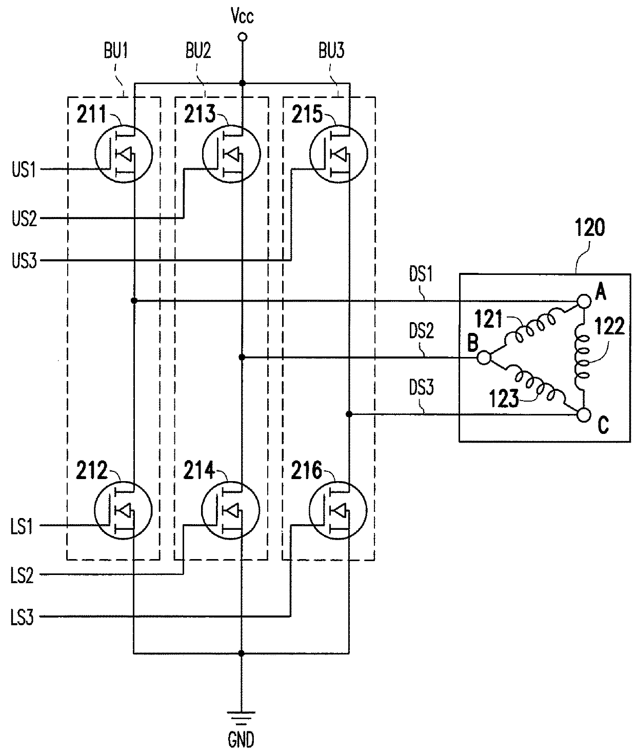
[0025]The motor apparatuses provided in the following embodiments of the invention may be used in electrical products, such as a grinding machine, a hair dryer, a range hood, a vacuum cleaner, a fan, and so on, but not limited thereto. Hereinafter, referring to FIG. 1, FIG. 1 is a circuit block diagram of a motor apparatus 100 according to an embodiment of the invention. The motor apparatus 100 may include a motor module 120 and a motor driving circuit 140, wherein the motor module 120 may be a multiphase AC motor module. Nevertheless, the invention is not intended to limit the number of phases of the motor module 120. For convenience of explanation, the following embodiments...


PUM


Abstract

A motor apparatus and a motor driving circuit are provided. The motor apparatus includes a motor module and the motor driving circuit. The motor driving circuit includes a plurality of bridge arm circuits, a temperature sensor, and a control circuit. Each of the bridge arm circuits is controlled by one of the first PWM signals and one of the second PWM signals generated by the control circuit and outputs a driving signal to drive the motor module. The temperature sensor senses a temperature of the bridge arm circuits and provides a temperature sensing value to the control circuit. When the temperature sensing value is greater than or equal to a threshold temperature value, the control circuit increases a duty cycle of the first PWM signal of one bridge arm circuit and a duty cycle of the second PWM signal of the other bridge arm circuits to lower the temperature.

Description

CROSS-REFERENCE TO RELATED APPLICATION[0001]This application claims the priority benefit of Taiwan application serial no. 106124332, filed on Jul. 20, 2017. The entirety of the above-mentioned patent application is hereby incorporated by reference herein and made a part of this specification.BACKGROUND OF THE INVENTIONField of the Invention[0002]The invention relates to motor technology and more particularly relates to a high performance motor apparatus and a motor driving circuit.Description of Related Art[0003]The existing motor driving technology usually utilizes the pulse width modulation (PWM) control technique to control the power switch element in the motor driving circuit for the power switch element to provide a driving signal (e.g., a current) to control the operating speed of the motor. However, when the power switch element is turned on or turned off in responds to transition of the pulse width modulation signal, frequently turning on and off the power switch element wou...

Claims


Application Information

Patent Timeline
Patent Type & Authority Patents(United States)
IPC IPC(8): H02H7/08H02P6/14H02P29/02H02P1/12H02P31/00H02K5/10H02P29/68
CPCH02P29/02H02P6/14H02P1/12H02P31/00H02K5/10H02P29/68
Inventor YEN, LIN-HAN
Owner FAIRWAY ELECTRONICS
Why Eureka
Try Eureka