Health monitoring

Active Publication Date: 2018-08-14
ISANSYS LIFECARE
View PDF21 Cites 60 Cited by
  • Summary
  • Abstract
  • Description
  • Claims
  • Application Information

AI Technical Summary

Benefits of technology

[0010]It is a particular advantage of the invention that the data processing means is powerful enough to be able to provide the key data while also being e.g. small enough to be sealed inside the substrate of the device. Accordingly there is provided an integrated device that may be comparable in processing power with a separate data processing/transmitting unit but which can be attached to a subject as a unitary device. The wireless transmitter may also be sealed within the substrate. The wireless transmitter may be provided separately or integrally with the data processing means. As a result of its integrated structure, the monitoring device may find use in a wide number of different medical situations, ranging from emergency monitoring in a trauma situation, to routine monitoring of a patient on a hospital ward, and to back-up monitoring of a subject in his or her own home.
[0011]The data processor has the function of processing ECG signals so as to provide key data relating to every heartbeat. Typically the most important raw data associated with an ECG signal is the R-S amplitude and/or time stamp for the QRS complex peak produced in the ECG by a heartbeat. The Applicant has recognised that processing raw ECG signals to extract the amplitude and time values associated with the R-peak for each heartbeat represents an efficient way to reduce the local power demand without compromising the data content that is transmitted. This data, in particular the R-R peak temporal spacing, can be used to calculate the heart rate (HR) using a relatively straightforward algorithm and thus in some embodiments the key data may therefore comprise a measurement of heart rate (HR).
[0012]However, in other embodiments it is preferable to minimise the calculations that are carried out by the data processor in the device and thus key data comprising the time stamp for the QRS complex peak is preferably sent by the wireless transmitter to be further processed elsewhere. Furthermore it is advantageous for the key data to include at least one piece of amplitude data in addition to the time stamp of the R-peak. In a preferred set of embodiments the amplitude data is the value of the R-S amplitude in the ECG signal, as a peak detection algorithm run in the processor may conveniently identify the R-S amplitude in order to determine the temporal position of the R-peak. Thus according to a second aspect of the present invention there is provided a cardiac monitoring device comprising: a substrate; means for measuring ECG signals; data processing means comprising a data processor; and a wireless transmitter; wherein the data processing means is sealed within the substrate and arranged to receive the measured ECG signals, to process each ECG signal associated with a heartbeat in the data processor to provide key data relating to that heartbeat, and to provide the key data to the wireless transmitter for transmission, wherein the key data is the R-S amplitude and time stamp for the QRS complex peak produced in the ECG signal by a heartbeat.
[0013]The processor may be programmed to run a peak identification algorithm that can identify the QRS complex in the ECG signal (shown in FIG. 1). In particular, a windowing algorithm can make use of the fact that the range of amplitude values in the QRS complex is, in a normal sinus rhythm, substantially gre

Problems solved by technology

In the context of cardiac monitoring using electrocardiography (ECG) electrodes, especially self-adhesive electrodes, wireless transmission of the raw ECG readings is possible but to transmit the entire ECG signal requires large amounts of bandwidth and consequently the monitoring device must be able to provide sufficient transmitting power.
However this approach does not allow every heartbeat and its associated ECG peak to be recorded and potentially processed.
Such a quasi-continuous measurement of heart rate may not reveal cardiac arrhythmias or other information useful for clinicians.
It has been reported, however, that in previous attempts the i

Method used


Image

  • Health monitoring
  • Health monitoring
  • Health monitoring

Examples


Embodiment Construction

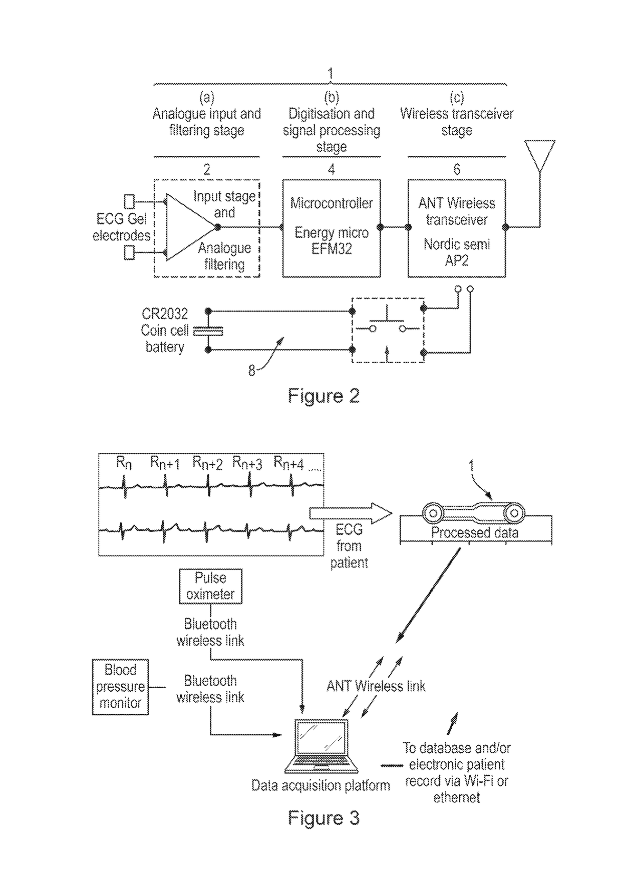
[0074]In FIG. 2 there is seen a schematic layout of the main electrical components of a cardiac monitoring device 1. The device 1 comprises ECG measuring means 2 including a pair of ECG gel electrodes connected to an input stage amplifier. An analogue ECG signal may be amplified and filtered at the input stage. For example, the millivolt level signal from the ECG electrodes may be amplified while 50 / 60 Hz induced noise and higher frequency muscle noise is filtered out. The input stage 2 is designed to reduce the effects of motion artefacts and ensures that the device 1 is suitable for ambulatory as well as stationary subjects. The construction of the device 1 is described below with respect to FIGS. 5-8.

[0075]The amplified and filtered ECGs signal are supplied from the measuring means 2 to a data processing means 4 comprising a data processor including a microcontroller such as the EFM32 from Energy Micro AS. The microcontroller is designed for very low power operation. The measurin...


PUM


Abstract

Health monitoring devices allow for monitoring of the vital signs of a subject. Wireless devices can enable a subject's cardiac and/or respiratory functions to be monitored remotely, e.g. without the subject being attached to bedside equipment. A cardiac monitoring device may include a substrate, electrodes for measuring ECG signals, and an electronics module including a data processor and a wireless transmitter. The electronics module is sealed within the substrate and arranged to receive the measured ECG signals. Each ECG signal associated with a heartbeat is processed in the data processor to provide key data relating to that heartbeat. The key data may include the temporal position of a characteristic feature in the ECG signal. The key data is provided to the wireless transmitter for transmission.

Description

TECHNICAL FIELD[0001]The present invention relates to health monitoring devices which allow monitoring of the vital signs of a subject, particularly although not exclusively to wireless devices that allow a subject's cardiac and / or respiratory functions to be monitored remotely e.g. without the subject being attached to bedside equipment.BACKGROUND OF THE INVENTION[0002]In recent years there has emerged a new class of small body worn devices that monitor one or more vital signs and transmit the readings wirelessly to a receiver unit without encumbering a patient with cables. For example, wireless and self-adhesive electrocardiography (ECG) monitors, which are placed on a subject to permit the remote monitoring of cardiac rhythm, are known e.g. from U.S. Pat. No. 3,943,918. A short-range wireless connection such as Bluetooth™ may be used. Typically the wireless receiver unit retransmits the data to an IT system for processing and display. The data (raw and / or processed) may be stored...

Claims


Application Information

Patent Timeline
IPC IPC(8): A61B5/04G06F19/00A61B5/00A61B5/0456A61B5/0402A61B5/024A61B5/0245A61B5/352
CPCA61B5/0006A61B5/0402A61B5/0456G16H40/67A61B5/02405A61B5/02438A61B5/0245A61B5/352A61B5/318
Inventor CHEFLES, ANTHONYMORRISON, RORYWEIR, REBECCAERREY, KEITH
Owner ISANSYS LIFECARE
Why Eureka
Try Eureka